Wednesday 8 June 2016

Tear down of (and how to calibrate) a Maplin/Precision Gold N73B Multi Meter

The N73B! I've had this little meter for a while now, and I think I cost me about £15 when I bought it.

Reason for buying it: well it was cheap, I needed something I could throw in a tool box when I went trailing, and seem quite rugged;as you will no doubt see from the oil stains this thing has!

Now it claims from the Datasheet to be CAT III rated, though I've never really trusted that, even when testing the circuitry on the HAMEG! If it went pop, then so what, £15 and no funeral held! All I had to do for testing that scope was to not hold the damn thing whilst testing high voltages!

But this thing keeps on going and going and GOING! Dropped, bounced, kick across the floor, thrown into a toolbox so many times, stood on, its been thoroughly abused!  So I thought I'd treat it to a set of fresh batteries and a bit of a calibration!

Why calibrate such a shitty DMM? Well I was more interested in how far out it was, if at all. Meh, call it shits a giggles!

Attempt at calibrating

On my bench at work is a KEYSIGHT 34470A - which I think most of you will agree is a shit hot DMM! Its less than a year old from the factory, and came with a calibration certificate. So safe to say if this thing says something is 1.234567V, it is safe to assume it is exactly that (within it's own tolerances)!

Using this as the standard I gave it a quick comparison after putting in some fresh AAA's. I simply just hooked up a bench supply and compared the 34470A's readings to the N73B's:

Well that's no fun: seems to be reading with the N73B's spec! I expected it to be more than that out after the years of service! So calibrating this seems to be a bit pointless, it seemed to be reading within its own tolerances. Still I wonder: what if you wanted to calibrate this? And I couldn't resist taking it apart and looking inside!

From the outside, it's pretty hard to figure out where to start! But after some gentle prying on the probe clips, it came away to reveal a single screw. Once that screw had been undone, I had to peel the decal away from the lower half of the meter, to gain access to its internals:


With the upper case removed you can still operate the DMM, but you may have to push the PCB down so the battery terminals make good contact:


So you will notice the non-contact voltage detector antenna (INT2) above the 14-pin IC (U2) and the white LED next to the Crystal (X1), that's the built in torch (which can be handy) and directly below that, the black cylinder is the buzzer (BZ1) for button press sounds, auto-shutdown warning and continuity alert.

Anyway, trying to calibrate it: I found 2 trim pots. My guess was that one of these was bound to adjust the reading...

 VR1 looked promising! With some small adjustment I managed to alter the reading on the display:
Success! OK! So how far has my tweak put out the readings on other ranges?
5V? ok that's within spec!
10V? Yep, that's ok.
15V?yeh that's ok, still in spec.
20V? Good!
30V? Fine too!

So my adjustment hadn't knocked it out completely, so I thought I best not tweak it anymore. As a belt and braces I checked the current too:


Although at 20mA and 10mA it would be considered quite bad for a higher end meter to give that reading; its actually within spec, and at uA range is not far off either.

 Whether or not my adjustment of VR1 altered the current reading too, I don't know. But I just wanted to check the current still read right.

A closer look

Ok for those who want a nosey inside! With the upper half of the case off, the PCB with yellow front cover protecting the LCD just slides out of the bottom half.
 
The leads are soldered to the front facing side of the PCB before passing through the PCB itself through 2 holes. The green device is a PTC and the orange is a MOV.
And over the other side of the board is a poly fuse, rated to over 2A I think, markings are barely visible.
 6 self tapping screws hold the cover that holds the switch mechanism to the PCB and covers the LCD.
 Notice that all bare contacts are gold plated? That's a point awarded for robustness of design! Don't want your contacts getting grotty now!

LCD backlighting is taken care of by 2x 3mm white LED's above the LCD.
Nice thick insulation on the lead wires...
Put a ruler against it to measure the clearance between the solder joints and at near 13mm, I think that's wide enough for 1000V rating(considering its 5mm minimum)

Overall

With regards to calibration - is it really worth sending this off to get calibrated, when its highly likely you'll be quoted the price you paid for it (if not: more)?

NO, its not worth it!

Is it worth calibrating it yourself? If you have access to a pretty hot DMM to compare? Sure why not, depends how attached you are?

With regards to its build: Its a tough old thing! Mines been properly abused and given the calibration is set with those SMD, single turn trim pots, that didn't even appear to have any adhesive on them to hold them in position, I was expecting it to be more than it was out! 

It also appears to be exactly as specified! Usually these cheap meters give specs on the case that are total bull! But this appears to be exactly what it says on the tin! So it looks like it would have handled some of the high voltage in the HAMEG!

For a 3.5 digit meter, that you can throw in a toolbox, and you know won't break if you do, its worth the money!

Should you get one? Ahh go on!

Now before this turns into a review, I'll leave you to it!

Take it easy!

Sunday 5 June 2016

DSO138 Scope Stand

So awhile back I bought a DSO138 scope- yep those cheapo DSO kits you can get off eBay or Amazon or Banggood.


Its basic, very slow and buggy: I managed to make the 0V marker offset itself some how, but with a firmware upgrade, this might clear this. But it at least it has storage capability and can measure REALLY slow signals, to the point of it being a data logger, which is really what I was after! Soldering it up keeps you out of trouble for a few hours!

After Building it up and testing it, I thought I'd best put a case round it, or at least to stop the bare PCB touching the work bench.

Now before I spent a few hours trying to design my own, a quick google search found a fella by the name of +Igor Kromin, who had already done a pretty good one on his laser cutter.

I modified his design to include a couple of angles so it can be placed on the bench at 45degrees, so your not having to peer over it. You can download the .dxf's here: https://drive.google.com/open?id=0BzyxjZtGh0xEWWUtV3pwdjJpU2M

So after carefully choosing so offcuts of 3mm perspex and getting the shapes cut off on works laser cutter...
I screwed the board to the base and sandwiched the scope between the clear piece. Screwing it down caused the clear piece to bend, not ideal.
So I found some nylon standoff's, which were a bit too long so had to file them down so that they just stood the clear piece just enough to just touch the LCD on the scope.

 
 The PCB did need standing off the back piece, so that was taken care of using some M3 plain washers. The whole thing was bolted together using some long hex socket head bolts, some flat washers, spring washer and nut.
I then stuck the angle pieces on with some Araldite. I much prefer Araldite over super glue in this application as it has more give and is less brittle.
After a few minutes the glue had hardened and the stand was finished

Looked pretty good, the angle was just right. Now it'd be good if I didn't have to connect power to it...maybe make it battery powered?

Anyway, that's another project.

Take it easy folks, catch you later!

Thursday 2 June 2016

First Power Supply Project - pt1: spec, design and testing theory


So I finished my first Power supply based project the other day and thought I'd start with a modest one. Here's how it came out:


I've decided I'm going to split this one up into 3 or 4 parts as its quite long winded for one sitting! so first off I'd thought I'd cover the design considerations, some specifications and testing.

I wanted a power supply that:
  • have an adjustable output that went as close to 0V as possible and have a maximum output of 20V
  • have current limiting
  • Could fit in the small aluminium enclosure in my parts bin
  • Be constructed and designed out of as many salvaged parts as possible
  • Be based round 1x quad packed op-amp - why make it easy yeh?
Now there are loads of designs out there, so picking is as easy as punching the right terms into google. The most popular of which seemed to be Dave Jones +EEVblog based design, which is based round an LT3080.
A popular design but I wanted to tweak it a little

Not having one of those in my box I decided to base it on an op-amp and pass transistor instead. So you could say a less polished version of the EEVBlog design.

Hunt for parts

After a rummage round my parts bin I found a 18V 20VA transformer which would be perfect to power my design. I needed an enclosure and the enclosure I was going to use for my Load project seemed to tick all the boxes: light, small, robust and the transformer fit inside! So that put 2 high value components off the shopping list!
Remember this?
Pass transistor: found a TIP3055. Seemed to be up to the task. The next high-ish value item was the heatsink. The transistor may have to dissipate up to 25W (18x1.41 = 25.38V x 1A = 25W and a bit, I'm assuming full load at near 0V output).

Then looking at the enclosure, the answer was staring me in the bleedin' face! I know working out the case thermal resistance was going to be a brain ache, so I didn't bother! Its a big chunk of metal with a large-ish surface area on the top! I just went with my gut - admittedly that's really not what your supposed to do, but if it didn't work then I was confident I could figure something out!

Other parts: well there are always resistors and caps, but I need a quad packed op-amp: LM324 - yep got one of those! Also a good power supply is based on a decent voltage reference. I didn't want to use a Zener as a reference as their temp coe. and initial accuracy can be poor and after some careful sorting of my parts I found a couple of AD680's. Very nice! Good temp coe. and initial accuracy!

The temperature in my garage can range from bloody freezing to quite comfortable in the space of a day and I'd rather not have my output be dictated by the weather!

Testing the theory

As with all designs, you first get some testing done. Using SIMETRIX I started testing some designs and observing their performance.
I went through loads of versions - this is version 5


My main hurdle was figuring out why my output voltage was so noisy. Then it became apparent I'd not thought about how my voltage feedback was working. Originally the feedback to my voltage error amp (X2) came directly from the output of the supply. When running the simulation and observing the output I first thought that I needed some filtering in my voltage feedback (C3) as from the response I got:
When you think your on the right track, you sometimes find yourself still going in the wrong direction!
But after looking at the design I was basing mine on, it was clear what I had done wrong! So corrected the feedback and removed C3. I then found that the output became much more stable!

Further simulation also showed that my output needed some regulation current at low voltages and some damping in the voltage amp feedback. Below is a revision of schematic version 5 (above) with the constant current source I1 set to step through  different values of regulation current (0-10mA) and C3 is now a 47uF cap connected to the non-inverting input of X4:
V5 rev1, C3 is now 47uF and position moved and I1 will step through on simulation
Firstly I wanted to see how the output voltage responded to different regulation currents. So I firstly I ran a transient simulation without C3 and set the source V4 (my reference) so that I would get approximately 1V output, and obtained the following:

As it can be seen, that having even a small regulation current on your output means your output voltage will regulated properly, it can be seen at no regulation current that it never reaches its set output voltage!

Obviously the rate at which it falls towards its set point is proportional to the amount of capacitance on the output and the regulation current (falls faster at higher reg currents). My design has quite a bit as you can see (880uF = 4x 220uF) as I would like as little ripple as possible on my output under max current output.

As it can also be seen there is a lot of overshoot! The transient response shoots up to 1.5V and then slowly falls. This is NOT IDEAL. At higher voltages above 1.5V, this overshoot was not as obvious, but voltages below 1.5V it was very apparent! Not good for testing low voltage, sensitive devices.

This is where C3 47uF cap comes in. I added this cap to the feedback loop for X2 and there was a vast improvement in overshoot:

So as it can be seen, with no reg current it still doesn't regulate the output properly, but is not as high. As reg current increases, the recovery from overshoot is quicker, however, too much reg current and there is a tiny bit of undershoot too, so you get some oscillation, but its hardly noticeable.

The overshoot is much less: <100mV.

Feeling devil-may-care I increased C3 to 470uF to to see what happens on the output:

All the different traces for the output for different reg currents are on top of each other, except the case where there is no reg current. You can see the again the overshoot is less (nearly 0 in fact) and that the 0 reg current output is also less. But look how slow the output takes to respond to the transient! That too is not ideal.

One thing that is also apparent with no regulation current is that the output when the set point is 0, is floating about 100mV above 0V, which can be seen in all simulations; another non-ideal case.

I tested the current limiting circuit and the response was as below:
V2 is the set-point of the current limit amp X1, again I ramped I1 (now acting as load current), for each step of V2.

Its a bit strange as 2 of the traces go below 0V, but still they are roughly what I was expecting, but a bit off. I'm not too concerned about how well it current limits.

I don't tend it use constant current mode an awful lot, I'll be mainly use it to ensure that the device I'm powering doesn't overload. So so long as the output voltage goes down once current limit is reached these results are acceptable.

Conclusions

So I settled on 47uF for C3 and a reg current of 10mA. So armed with this schematic and data I moved into CAD.

Goes to show that testing does help refine your design, help understand what's going on and also learn a little bit about the process. I learnt that small amount of regulation current is important and why. Doing it in a SPICE environment also takes the pain out of getting things wrong and having to replace parts on a bread board for example.

I must admit that most of my simulations were based on suck-it-and-see testing, but that's sometimes a good way and if you have some idea of how it works then understanding what's going on becomes apparent.

So in the next part I'll go into the CAD and  what further design considerations I chose.

take it easy!

Wednesday 1 June 2016

Where have all the caps gone?!

The past few weeks I've been doing a stock take at work. One of the things I need to replenish is low value caps between 1pF and 10pF.

You know the kind - Orange ceramic beads stood proud on 2 wires, usually 2.54mm or 5.08mm apart:
You know they could be mistake for an NTC. The reason I want these types is that they are good for bread boarding and prototyping - something that gets done a lot in a teaching lab.

So what's so hard about that?

Well recently I've been trying to find such caps of these values are I've constantly come up with results from the big suppliers (Farnell, RS, Rapid) of either out of stock, no longer manufactured, long lead time, coming in from elsewhere with a £15 delivery charge, or the wrong voltage (which also means they are 10x the price of the little orange ones).

So what's happening?! Are they being phased out? If so how are we supposed to supply lessons without either breaking the bank ordering high voltage values, or ordering without incurring stupid delivery charges?

What I want to know is:

  • why are they now so hard to get hold of now?
  • Are they being made redundant cos of lack of sales over SMD values?
  • What's going to happen in teaching when they are finally phased out? you can't breadboard a 0603 cap easily!

Friday 26 February 2016

FTDI Gate - the aftermath!

Some of you are like me: I love a good F*&k-up story! Case in point: VW Diesel-gate.

When established companies drop the ball and do it big time, there's this sudden interest of who, what, why and when. There's no sense of gloating with me (unless there's and axe to grind), but it just interests me the thought process one or a group of individuals took before they realised: "Shit! Maybe this was a bad idea!"

So when I first heard about FTDI gate I took a major interest in the debacle!

Who are FDTI?

If your asking yourself this question, then I'll explain.

FTDI is a small company in Scotland developed by CEO Fred Dart. Before it was FTDI, it started out as one-man consultancy, making hardware for PC mother boards in mid 90's when the PC boom was in swing. After a while Fred decided to go into silicone design and started churning out IC's for customers.

After finding his feet it seems, he then went on to design his own brand of IC and FDTI was born. When the USB standard came along, they found their niche and went for it (albeit after a shaky start).


Since then they have dominated the market with their range of USB based products and have become one of the #1 USB peripheral interface/driver of choice. Their offices are now around the world employing about 400 people..from an original number of 5!

I've used their products making a few test rigs and programming aids - they are the mutt's nuts! if you are using a USB mouse or keyboard right now, chance are high it has an FTDI interface in it.

OK so what happened?

Well the problem with branded products that do well, to the point that even generic branded products get called "FTDI...USB" is that they suffered from counterfeiting!

In October of 2014, Hackaday reported a USB driver update that FTDI released, that came with an important windows update, was found to be bricking peoples "FDTI" based devices without any notification. They just stopped working

It then transpired that FDTI was responsible...and there was a shit-storm!


FTDI admitted that they had released this drivers function intentionally!

The short version of how it did this was the driver somehow queried the device for its credentials and if they were incorrect,  it set the devices internal PID number to "00" which essentially made it a null device.

Its like changing your house number to: 0, The High Street, unknown town, unknown county! You could go to that address and see it, but you probably would be able to send mail there! 

People in the middle of important projects could now no longer do their work, people who'd used their chips in products were inundated with complaints from customers.

Literally thousands and thousands of people who had up until now had happily been using there USB interface devices, now had a piece of ceramic and silicone where the once working USB interface chip had been. They were now as much use and a pebble on a beach!

Even swapping it to another computer did nothing, the device was well and truly FUBAR'd.

However some people reported that this was not happening to their device...so what was up?

So why'd they do it?

Well it has to do with the counterfeit IC market.

Some of you (the uninitiated) will scoff at this:

Nobody in their right mind would bother to counterfeit IC's!"

Well it's not like going down to Costco, bagging a load of white T-Shirts and getting your mother to iron Nike transfers on them, then bunging them on ebay ...well maybe it is, but its a bit more clever than that!

Tricks and traps!

They can come in different guises:

Failures from a batch of IC's from a reputable manufacturer can be resold under false advertising. Hard to identify, though I believe they wouldn't have a date code on them?

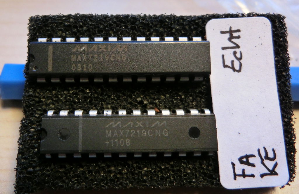
Low end versions of a device similar to what a high end manufacturer would sell get snapped up, the tops scrubbed off them and branded information laser over it or if in a plastic package: the package is removed chemically or thermally and a  plastic outer layer is reformed and branded data printed on the casing . Usually identified by uneven lettering and remaining flash from the injection process. Though now its getting hard to identify!


Recycled - devices may have already been through the mill! usually can be identified by solder that remains on the pins


Complete professional hack-job: a sub-standard design is developed and made in poor quality manufacturing conditions and they just brand the package with a popular brand. Nike-transfers-on-cheap-t-shirt method!
Could you tell?


And the down right dastardly! SOLID COPPER DIE! I kid you not, I have read an article I now am unable to find where a small batch of IC's were delivered fitted, shorted out the boards, the plastic casing removed to reveal a solid copper block with all pins connected to it!

FTDI's CEO stated in an interview with Lada Ada that a customer complained that there FTDI chips were not working to specifications outlined in their datasheet and wanted to verify with FTDI.

So FTDI tested them and low an behold they did not achieve par and after sending the chips off to be de-capped (basically filing the top off!) found that the physical architecture of this batch was not theirs, along with device ID's not matching batch records and the big give away: made in China on the bottom!
A close up of decapped IC with the exposed die.
The secondary issue was that these counterfeiters illegally using FDTI's drivers essentially tricking the driver software into thinking that it was talking to the genuine article!

As such FTDI decided to act to stop these chips from being used and force the counterfeiters to stop reproducing this sub-standard version of their chip. They did some clever (and secret) jiggery-pokery and interrogate the device. If the answers are incorrect then you WILL BE SHOT...no wait..sorry...BRICKED!

Then what?

Well I already explained that a shit storm kicked off! I mean, just look at the comments on the original hackaday article. People were livid that FTDI, company that they felt they could trust, were literally taking their tools by proxy! Basically: borderline theft!

But the people fought back! Not even 2 days after, those clever subscribers to Dave Almighty's EEVBlog forums and figured out how FTDI had bricked the chips!

This then lead to the next logical step of how to get round it!

Back to square one for FTDI then...and now with less support from its customer base than before.

Sheepishly: FTDI backed down, stating that they had got Microsoft to removed their drivers from the windows updates and that their "intentions were honourable".

Then there was nothing for a good year and a bit, until Feburary of this year Hackaday reported that FTDI were back at it, only this time they chip was not bricked as such- more identified as a non-genuine chip. The device can still be used on linux based systems or by turning windows updates off, but at least it didn't brick the device completely - some mild disguntlement from some people.


so now your up to speed!

My 2 peneth

I'll admit now, When I heard about FTDI gate MK1I was livid!

A company I thought was one of the good guys had single handed managed to damage my faith in them by them forcefully removing peoples tools (and thats essentially what they are) from them and these people probably had no idea that they were in the wrong and were most likely totally innocent.

"All they did was buy what they thought was the genuine article at a cheap price and most likely had no idea that it was knock-off. Heck even honourable suppliers probably thought the same!"

After I read Lady Ada's interview with Fred Dart and recalled my words and feelings from the original scandal, it suddenly dawned on me:

WE AS ENGINEERS, HOBBYISTS, & TINKERS ARE THE REASON THIS SCANDAL EXISTS

Right has that sunk in? Still pissed off at me for saying that? OK but before you go down to the comments to unload a tirade of bile my way, let me explain something and I'll start with 3 letters and 4 numbers:

ISO9000 "is a series of principles of management that a company must adhere to to meet the needs of customers and stakeholders whilst meeting statutory and regulatory requirements related to a product."

"SO!?"

So these principles are there to ensure that the source of these parts adhere such requirements including a standard of working environment and management.

Companies such as Farnell, RS, Rapid to name a few are ISO9000 or 9001 certified and as such will only deal with manufacturers who are likewise certified.

Lets paint a picture: Farnell decides to buy a batch of plastic brackets from India without going out there and seeing the factory for themselves. They place an order for 10,000 units. After 2,000 units sold, it turns out from a news report that that factory had substandard working conditions, multiple counts of health and safety violations, children under 10 years old working 16 hour days instead of being in school and using recycled plastic bottles to make the brackets using old machinery that should have been scrapped years ago!

Their shares plummet, Farnell file for bankruptcy, and yes would probably mean good parts going cheap, but in the long run: not good for Farnell, its shareholders and more importantly its employees!

"Your point being?!"

The point is that we as electronics people always want the cheapest we can get! 

I mean why pay £15 for it off RS when you can get it for £6 off ebay on slow boat from China, right?

But do we know who exactly we're buying off? As far a I can see on sites like Ebay, Amazon and other market sites - sellers don't have to be ISO9000 certified, why would they need to be right? 

Of course, you don't go down the veg market, ask the guy yelling "PAND A PUNNET!": "Excuse me chief? Are you ISO9000 certified?"

One: he'd tell you to buy a punnet or bugger off, and two: he's a one man show, and probably his kid and wife. No management system, nobody he pays wages to!

With market sites, you just fill your boots with cheap kit, not giving a second thought to where the seller has sourced it, who's made it, where they source their components from (counterfeiters)? Are the people making it getting a fair wage and  safe working environment? Are those employees of legal working age? is the company supplying those components paying their tax bill? Cos lets face it there are some unscrupulous bosses out there who will cut any corner to make a profit fast!
So my point is with regards to the FTDI issue is they have exposed how tight fisted we are! yes they went about it a bit ham-fistedly, maybe a different approach should have been taken.

But this is someone's company they built up from a one man band to a 400 man company supplying IC's to some well known manufacturers! And also what would you do if you caught someone using and selling something of yours they'd not asked to use? You'd take it off them!

You like a companies product, buy through a reputable supplier and buy a the price they're asking! Still too steep? Try a different well known supplier, they might have ordered a bigger bulk and have it on offer!

So your so-called FTDI UART cable now doesn't work cos FDTI knacked your drivers. Your Shitty Arduino knock off Amazon that took 3 weeks to arrive now won't connect cos, yep, FTDI bricked the interface chip!

So for all those kicking off at FTDI, Bear this in mind: you got it off Ebay for a song! What did you expect?!

I'm not saying all ebay and amazon sales are bad, hell I've got some stuff coming from ebay, but I know for a fact they aren't branded at all and I didn't cough up a lot, so if it falls over or goes pop: meh! I won't go shouting my head off at Linear Technologies anytime soon when my buck convert falls over!

But you really have to ask yourself - why so cheap?