Monday, 8 June 2015

Grumblings

I guess you could call this my first video blog. Here are some ramblings about taking an engine out of my mini cooper.
So after I managed to get an engine hoist, kindly lent by my neighbour, I pulled the last nuts a bolts holding the engine in and single handed coaxed the engine out:
Good day to pull an engine!Glorious!

Flying engine!
Given the alley down the side of my house is too narrow to get the hoist down I had to find the wheel barrow and use that to get the engine near the shed. Well i wasn't just going to leave it on the drive way!

Mental power to weight on this baby! lol!
serious weight loss!
The damn thing is heavy! About 150kg. Wheeling it out to the garden in a barrow took about 15mins by myself. Once in the garden I wheeled the hoist into the garden and lifted it out of the barrow and onto the hoists beams with some wooden joists.

Once in position, it was a case of relocating the tools to the garden and begin removing the offending bolt from the starter to remove the gearbox from the engine. and low and behold, the friggin' thing had been cross threaded!! I was bloody lucky I didn't shear it!
 I later managed to reform the damaged thread and tap out the hole in the bell housing, now it screws back in with ease.
night shift!
So with gearbox off, I could get access to the clutch, which a new one was fitted, 15 min job, and the gearbox was taken into the shed for further operation! A tarp round the hoist to keep the elements out of the engine. Good time to stop for a beer and chill out!!

Wednesday, 3 June 2015

Olimex are watching!

Cast your mind back to April of 2013....(cue wavy visuals!)

Yes I posted my brief review of the Olimex AVR programmer and programming a Bootlaoder to an arduino uno.

Well turns out I need to upload refer back to it as the ATMEGA328P-PU on my board has had a falling over and A0 is shafted - it either reads the upper 1/3 of the supply or low. So I'm going to buy a new one and burn a bootloader onto it using the Programmer.

Read through me old blog - Clicked on the link for the manual for the programmer, had a scroll down and saw this....
Look Familiar?!
YEP - the buggers at Olimex read my blog and took my bloody schema! Not that I'm pissed off, more that they could have said thank you!

Not to worry +OLIMEX  (didn't know you were on google+), glad I could help!

Tuesday, 2 June 2015

Precision Voltage Reference

So +Scullcom Hobby Electronics released a video about updating the voltage reference he originally designed. And after a rummage in my parts box, I managed to find a few more IC's that should do the job:

A Little Rummaging...

Primarily I needed a voltage reference: I found a REF03GP - 2.5V reference with an initial accuracy of up to 0.6% (15mV) and a Tempco of anywhere between 10 & 50ppm/oC - not the best but good enough, hopefully can trim it out.

Next on shopping list, Voltage doubler: I found three INA134's - like a INA105, but for audio applications. Seen as we are working with DC, I don't think this will be an issue. So now I can go from 2.5V, to 5V, to 10V using 2 of these amplifiers. Not sure how close the 10V will be after 2 stages of amplification, but will see.

Next; a split rail generator: closest I could find was a ICL7660 - meaning I could make a negative rail, but also means I have to generate my own positive rail. Hmmm... will have to do some digging or maybe design a voltage multiplier or joule thief?

Brief description of the circuit

I'll be using a 9V PP3 cell to power this project, with associated protection circuitry, battery monitoring and indication. The 9V cell will power the reference and the split rail generator.

The split rail generator will power the Op-amps only, so it doesn't have to be high power.

The reference will then be amplified once to 5V by one amp and then again by the second amp to 10V. I'm hoping that the 10V isn't so far out after the second round of amplification that it makes it useless, but we'll seen on the breadboard.

Proposed System


And then...

Once I've tested it on a breadboard, I'll then solder it up on some strip board and then stick it in an enclosure with some binding terminals

Monday, 11 May 2015

Its all in your head

This on is a little ranty so bear with....

I used to work for a guy that kept all his schematics in his head....either that or he kept them under lock and key an committed them all to memory. Either way, the day I started tracing out one of his circuit boards, he told me that: "it wasn't necessary".

I hate to break it but it is.....it really, really is. To this day I had my suspicions about why he didn't want them tracing...possible fear of being found out it was a copy? I don't know?

But if you want to design something, then you have to draw it out, for your sanity and everyone else's!

Draw your schematic!

I always get asked to help with somebodies circuit. Usually they tell me what it is (e.g. an inverting op-amp) and I can usually work it out. 

But sometimes I get some really big circuit, which in a student lab are on breadboard and are a complete rats-nest! When I ask to see the schematic, and they say they haven't got one (through that cheesy grin and that slight chuckle), I feel my shoulders drop.

It is a fundamental part of being an engineer - learning how to draw a schematic.

Be it a full blue-print of the Saturn five rocket, or the stick in the sand that was the first sketches of the land rover, it was drawn out and others could look at it and say: "Yeh that'll work!" or "if you swap this...". 

It means you get your fellow engineers, colleagues, prospective investors on the same page. And for when it all goes wrong, somebody (like me) can help out. And for when it all falls apart, at least you have something to refer back to. And for improvements; something to scratch those ideas onto and mark test findings on.

Yes, having a schematic  for development is:

VITAL!

But I can't draw...

You don't have to be an artist and draw out Da' Vinci type sketches. I have zero artistic skill yet I can still bash out a simple schematic.
Impressive, but for drawing a inverting amp based on a 741...nah!

For the prototype stage; you don't have to be a master drafts man to draw it either or use complicated CAD packages. All you need is a pen, a piece of paper big enough, a basic knowledge of electronic symbols and that's it!
Dave Jones fully utilising his copy of Dave CAD
Even Dave Jones on on the +EEVblog uses pen and a post-it note. Hell its not professional looking but its still a schematic.

OK, but I want to do a more professional looking schematic...

OK, that's good, a clear, professional schematic or drawing not only shows what your trying to build in better definition, but it requires some training and practise on the CAD package of choice.

There are a number of CAD packages available to draw a schematic:

EAGLE CAD - this is the CAD package I cut my teeth on. The tutorials are comprehensive and it offers a freeware user version. This version does only allow one sheet schematics though, but that schematic can be as big as you like! I'd put the user skill at mid-range, plentiful parts library and also Farnell/Onecall support EAGLE library parts with some of their catalogue.

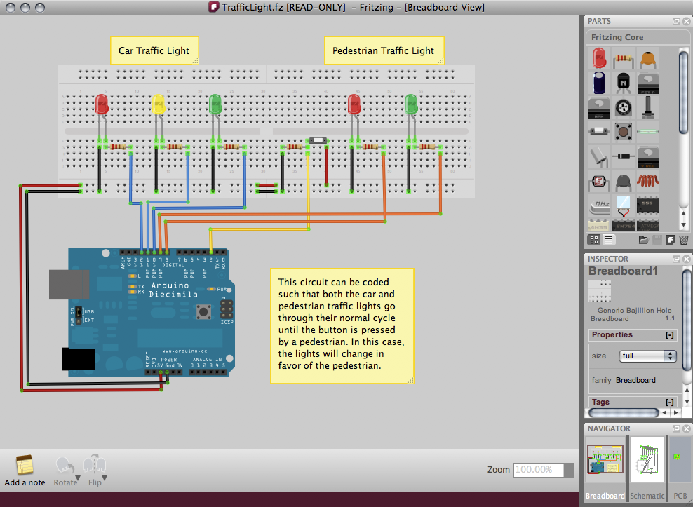
Fritzing - Fritzing is a free schematic editor that you can draw up on breadboard as well - this is good for prototyping for those new to electronics as you can pull out images of what it should look like on breadboard and translate that your prototype design! it is a bit noddy though and the parts range is not the most extensive, for that I put the user skill at beginner.

KiCAD - For Linux users. This is  suite of programs aimed squarely at electronics and PCB production. From the brief introduction to it, I find that its a bit more complicated and more involved (like applying your own component naming), than the other 2 and is a bit more like ISIS (Part of the proteus suite). Not the most up to date tutorial package either. This ones mid to experienced user skill.

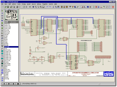
Proteus - This is the Rolls Royce of the 4. Full schematic editor (ISIS), PCB design (ARES), BOM Editor, Firmware Editor, circuit simulation, 3D layout view, its got the LOT! However, it comes with a Rolls Royce price tag! There is a demo version you can download. This one is the toughie to learn!

Whichever one you choose, its a skill worth having! Being able to generate CAD files makes you not only more employable, but more efficient and productive.

But for development, a simple sketch in your note book is just as powerful!

Friday, 8 May 2015

Bollock'sed to Brilliant!


Holidays! Great! Till you do something bloody moronic like go for a swim with your phone in your swim shorts pocket!! Good job there was free beer where we were staying! Fortunately pool water is not as corrosive as sea water, sea water...forget it, that thing is toast! If the water doesn't damage it, the salt on any electronics will get uber corroded and short out!


I soon as I realised what I had done, I pulled the back off it and let it dry out in the baking Turkish heat. That didn't do the trick, which was a surprise (24DegC outside! toasty!), tried to power and vibrated constantly, had to yank the battery out!

So managed to unscrew the screws holding the thing together (about 6x PH000 heads), and rather than straining my extremely poor Turkish for: "Please can I have a blow of rice grains?" I got one of the kids nappies (unused of course, which are rich in silica crystals to keep arse's dry all night long!) and wrapped the whole thing in it and left it for the rest of the holiday, only putting it all back to together and bagging all the loose bits till we went back.

Damage Report

  1. Went to power on after a week in a nappy and it booted! Audio notification could be heard but no screen. Screen was already cracked from dropping it on gravel, so water must have ingresses through the cracks and penetrated the screen.
  2. I looked on youtube for some video's on dismantling the phone (HTC 310 desire - see below). Managed to pull back cover off and remove the touch screen connector and the display connections - both had minor charring where they had clear short cos of the water and some tracks on the flexi pcb had come off! bad times

Old & Busted, New Hotness!


Thanks to our Ruski friend and an ebay find, I managed to fit the new screen for about £20!

The only issue I had was that the adhesive you fit the screen back on: as you can see from the video, its all gungy and very tacky! The only thing I could find was some equally tacky double backed tape, which I stuck in place and use a scalpel to remove the unwanted parts and cut holes for connections and the camera. It seemed to do the trick!

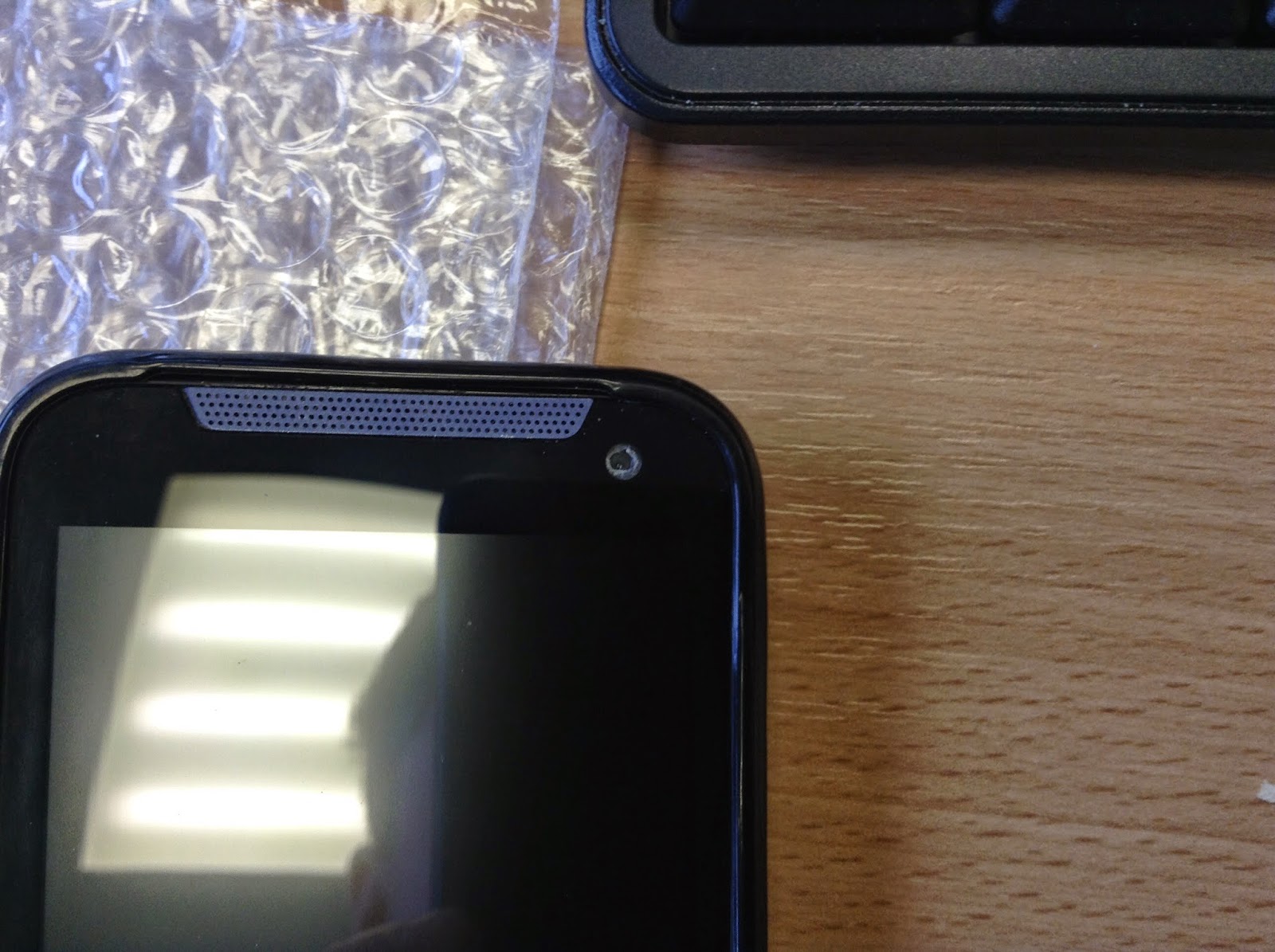
The only oversight was I didn't cut the hole out of my gasket big enough for the front facing camera!
Its crap anyway and never use it!

I tested the screen first by part assembling the phone and using the battery powering it and it worked! Display and touch screen, so my worries of the display and touch drivers on the motherboard being borked were removed!

The only down side - one single dead pixel....well for £20, I can live with that....till I get my upgrade!

So all in all for a £20 safe gamble I managed to save the ball ache of either forking out for a full repair, or worse, going back to vodaphone and trying to sort out a new phone or even worse a brand new contract!

Wednesday, 6 May 2015

What not to do...

Conversation I recently had:
ME: "so whats the problem?"
Student: "OK, so I'm running 5V to my logic circuit using a potential divider and......"
ME: "....pardon?"
Student: "yeh...can you do it that way?"
ME: "errr no...not really"
Student: "oh, ok.....why not?"
<Chris Proceeds to whiteboard and beckons student over.>

Why not to use a potential divider as a power supply

What is a potential Divider?


A typical PD circuit
A potential divider or voltage divider, produces an output voltage (Vout) which is fraction or ratio of the input voltage (Vin). This doesn't have to be 2 resistors, it could be as many as you like (look up ADC's and R-2R ladder networks), or even have capacitor or inductive elements, but for now, We'll just look at simple resistors.

Further descirption available on Wikipedia

Some Maths

Assuming that there is no load at Vout (i.e. no current flowing to Vout), the Current (I) flowing in this circuit can be calcualted using ohms law as the total resistance of the circuit divided by the input voltage:
I = Vin / (R1 + R2)     -eqn 1.

So we can work out the voltage drop across R2, which is Vout:
Vout = I x R2     -eqn 2.

Substituting eqn 1 into eqn 2 gives:
Vout = Vin R2 / R1+R2     -eqn 3.

This is the equation to work out the output voltage of the potential divider. Here is an online calculator to do the leg work for you.

So why can't I use it as a voltage reg?

Take Kirchoff's Current law, the sum of the currents flowing into a point equals the sum of the currents flowing out. So if you hook a load to Vout and draw current you can derive the total current as:
I = I1 + I2     -eqn 4.

Case study
So say you want 5V as Vout and you input voltage is 12V. This means you can use a 7k for R1 and a 5k for R2 (not E-series, but it makes the maths work) - that's ok. But what happens when you specify a current for I1?

For this I will use SIMetrix (a Free circuit simulator, worth a look, definitely read the manual and tutorials) to simulate what happens rather than explain:
the PD circuit (Ignore X1 its for the POP calculations)

Probe1 = Vout, IPROBE1 = Total circuit Current, IPROBE2 = Current in R2. I1 is a constant current source, this simulates the circuit that would be connected.

I1 is set to 0.5mA - a fractional amount of current, yet when I run the simulation:

PROBE1 is the red line, IPROBE1 is the blue and IPROBE2 is green


Though you can't see it, the IPROBE2 reports the current through R2 is about 700uA and the total current in the circuit is about1.2mA, but also notice how the voltage Vout is now only just about 3.54V!

If I increase I1 to 1mA, it gets worse for your "regulated" supply!

Now Vout is only about 2V! So why is this? Well your pulling more current though R1, which gives rise to a greater voltage drop across it. Given that:
Vout = Vin - VR1

Then Vout will get smaller the greater VR1 is!

I did try ramping the current I1 up and did get some silly results. 

To conclude

Don't use a potential divider as a voltage regulator - it just doesn't work! Leave their applications to reducing large voltage to a smaller voltage for measurement and setting ratioed voltages & references.

Tuesday, 5 May 2015

What supply to use - a brief overview

At work I get alot of students asking me questions about how to power their projects, why there power supply has blown or is not working, and how to power their projects off a battery.

So I thought I'd do some brief post about different ways of powering your project, the pro's and con's of each type and off the self solutions I would recommend for the new electronics hobbyist.

First off:

Linear Regulated Supplies

Linear supplies means the unregulated DC input to the regulator is - well - regulated to a stable constant voltage, without using any switching action, providing the input to the regulator is greater than that of the output.

A definition of an unregulated supply: the output of a rectifier, a battery, alternator or generator output - all of these will have a voltage but will not be constant over time.

A voltage Regulator can be analogous to a regulator on a divers air supply. The pressure in the tank is far greater than the diver would need to take a breath, otherwise it would blow their lungs! so the pressure regulator reduces the pressure to something sensible so the diver can take a breath without turning into a balloon! Likewise if the pressure in tank is lower than the pressure outside, no air will flow out of the tank (bear this in mind)

Why Linear

  • They are cheaper than Switch mode
  • less noisy - no switching frequency to be coupled onto the supply
  • simple
  • no inductive components

Why not linear

  • not very efficient - lots of power loss
  • very hard to handle high currents (as above), without having to add more components
  • not very good for battery applications (except maybe LDO's)

Cheap and Easy

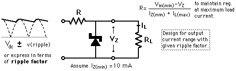
The simplest linear regulator is a resistor-Zener network:

I don't particularly like using these, but they are stupidly simple, uber cheap and zeners and resistors are always available. However you must check the Iz for your zener as incorrectly calculating R will mean your zener will not behave to spec. Usually the physical size of a zener can dictate how much power the circuit can handle. For low power, cheap and easy applications, this one is a winner.

if you can't be bothered working out the values, then this online calculator takes the leg work out of it.

A Little more refined

A better way of regulating your supply is to use a voltage regulator:
This is a typical circuit for one. It does look more complex than the Resistor Zener network, but its pretty elementary: the op-amp basically drives the transistor till its inputs are equally balanced. The inverting input in this case is connected to a resistor zener network as before, but only this time there is no load current (assuming infinite input impedance one the op-amp). When the voltage at the non-inverting input reaches the same as that of Vref, the op-amp stops driving the transistor, till the supply drops. the process is very quick and linear.  However you don't have to build this circuit each time as it comes in neat, cheap little packages. 

A typical regulator circuit is shown below:

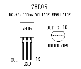
Linear regulators are the easiest to implement. Take the humble 78xx (where xx is the voltage it regulates the output at) series of voltage regulators: these come in the common TO-220 package (for beefier application) or TO-92 (for lower power applications, Usually noted by the L suffix):
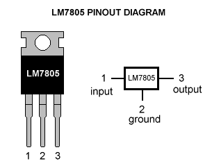
TO-220 package 7805 (+5V) with pinout
TO-92 78L05, similar package to that of transistors, with associated pin out.

The 78xx series is the most common, cheap and readily available type of voltage regulator, so a good place to start for a simple DC-DC step down, but there a few things to consider:

Considerations

  • As with the diver air-tank analogy: the input voltage must be greater than the regulated voltage.
    • All linear voltage regulators have something called Vdo or Vdrop (or the drop out voltage). This is voltage drop across the regulators output to input. If you have a 12V-ish input and the output of your regulator is 5V (7805) then your Vdo = 12v - 5v = 7V. 
    • If you look at the datasheet for a 78 series regulator, You will find that the minimum drop voltage is 2V - so for a 5V regulator you MUST have a minimum input voltage of 7V
  • With Vdo in mind you must also think about the power dissipated in the regulator itself
    • So say you building a USB charger for your car using a 7805 (which is a valid design) so you require a current of 500mA max on the 5V output, and your input voltage is max of 13.4V (charger running off alternator)
    • Pulling 500mA at 13.4V means the Power dissipated in 7805 is going to be: (13.4 - 5) x 0.5 = 4.2W! Your regulator is going to get a bit toasty and will probably reduce its life expectancy.
    • So how to get round it? Well you could screw the body of the 7805 to a heatsink, the car chassis in this case is ok (providing its a negative earth chassis), or you can reduce Vdo or your output current. A cheats way of reducing Vdo over the regulator is to put a resistor in series with the input of the regulator to dissipate some of the power in the resistor instead of the regulator, thus saving it from a quick death! This resistor will need to be rated correctly. 
    • Alternatively you could opt for a LDO or low drop out regulator
  • If you have inductive or large capacitive loads on the output of your regulator, you might want to consider using a flyback diode across the regulator:
    • Inductive loads like relays and motors can cause spikes which give rise to reverse voltages. Regulators don't like these much.
    • Same applies with large capacitive loads, the fly-back diode can direct current from the capacitors back to source when the source is turned off.

Low Drop Regulators (LDO)

Low drop out regulators have a lower Vdo which means that you can afford to have a smaller input voltage before the regulator stops working. This makes it good for battery applications, typically where a 1.2V or 3.3V supply is required (so your not using an obscene amount of batteries).

An example of a LDO I've come across is an LD1117V33, where its Vdo is 1.1V, nearly half that of the 78 series. Some can go even lower (0.8V).

So bear this in mind for your application.

POOOWW-EEERRRR!

OKAY! ok! so you want more power out of your regulator, yeh? ok well going to have to add some more components and pay attention!

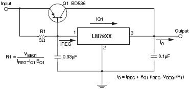
Typically what you can do is add a by-pass transistor to essentially divert some of the current around the regulator:
Typical by-pass transistor on a regulator circuit.
The short of it in this case is once the current through R1 gives rise to a large enough voltage to turn on Q1 (basically: Ireg R3 > Vbeq1)a current path opens up from the input to the output through Q1. However your transistor must be beefy enough to manage your power requirements: a TIP32 could handle decent amount of current, but a MJ4502 or equivalent could handle a helluva lot more.

When Q1 is on, the output remains regulated by the Vreg. When I first studied this circuit a while ago, I had trouble understanding how it worked as I though the transistor would just pass the input tot the output.

Ideally R1 should be calculated for your regulators max current rating and your by-pass transistors Vbe. Also you have to rate your transistors Vce correctly, no point in using one with a Vce of 20V if your input is 30V and your output is 5V, it'll just die!

So as a case study:
Say you have 30V coming from a rectifier and want a 5V, 3A and your using a 7805, rated for 1A, and you selected a suitable transistor to handle the extra 2Amps and calculated your value for R1, but what about the power disappated in your transistor: (30V-5V) * 2A = 50W! that thing is gonna get hot, so you are also going to need a decent heatsink.

If you look at the back of old Linear bench PSU's, you'll see that they have these massive heatsinks to dissapate the heat from the by-pass transistors:
An old Farnell TOPS2 PSU, massive heatsink on rear - these things are oldskool and tough!

This kinda drives home why linear PSU's are very inefficient!

Alternatively, you could revert to building your own regulator from scratch with an op-amp, reference, a transistor (or MOSFET) and couple of resistors, and pick a heavy duty rated transistor or FET.

Bit of a Boost?

If you want to boost the voltage output of your regulator slightly, you can place a diode in on the GND pin to GND. This will raise the output by 0.6-0.7V.
D2 in series with the GND pin to GND will raise the output by about 0.7V

This is good if you require a little more than the rated output to say transmit power of a long cable say.

Adjustable & Negative Regulation

The final thing I'll hit on is adjustable linear regulators and Negative voltage regulators.

So say you want 7.2V regulated from an unregulated supply. Not many 7.2V regulators out there are there? Not to worry: the LM317 is a glorious device that allows you to specify your own regulated voltage output! Not only is it an adjustable regulator, if you read section 9 of the datasheet linked above, there are loads of different applications you can use this chip for!

Here is a typical adjustable regulator circuit using an LM317 with pinout:
R2 here is a variable resistor which means the output can be adjusted on the fly between 1.2V and 25V. R2 can be a fixed value if you want a fixed output.

The typical formula to set the voltage output:
Vout = Vref (1 + R2/R1) + (Iadj R2)

Where Vref is typically 1.25V. The second term in this equation can be ignored as Iadj is in the region of 50uA, really small.

R1 is usually recommended to be 240R, not really sure why, but it works!

As with the other regulators, you can employ a by-pass transistor to carry some extra current to the output and as with other regulators, it has its limitations (Vdo and load current). A flyback diode to protect against inductive spikes and heavy discharges can also be employed into this circuit.

The down side with the LM317 is the minimum output voltage is 1.25V, not very good if you want to go below this, but still a cheap variable supply project can be made out of one of these.

The LM317 has some heavy duty cousins: the LM350 & the LM338 - rated at higher current capabilities and also available in TO-3 (Big Metal Can) package.
TO-3 metal package, pretty good for dissipating heat and bolting to heatsinks
All of the above regulators have their negative voltage counter-parts: the 78xx has the 79xx negative series, and the LM317 has the LM337 negative voltage regulator and work in a similar way.

Right, that's all I know for linear supplies, hope this is of some help to someone and thanks to all source for the pictures.