Tuesday, 2 April 2013

Olimex AVR Programmer

A bit of a Heads up!

Whilst messing around with this programmer, I found you can accidentally over-write the boot-loader on the Arduino by uploading your program through the ICSP header!

SO YOU HAVE BEEN WARNED IF YOU PLANNING ON DOING THIS! I DID NOT BREAK YOUR ARDUINO! It just needs the boot-loader re-loading! See below

Bit of Background

So with some up and coming Arduino project coming to a close, I want them to become stand alone widgets, where they can be soldered onto a strip board and utilise a controller of their own, like the ATtiny range of micro controllers.

ATtiny85 - Small, dip-8 package, really useful
You can program chips on breadboards using the Ardunino as a ICSP (In Circuit Serial Programmer: ICSP wiki definition)

I found this Link: Programming an ATtiny with arduino, a while back and managed to program an ATtiny85V with the Blink sketch in the Arduino IDE, which as proof enough that it could be done for me. Big thanks to those guys at High Low Tech, MIT!

However, this kinda makes your Arduino tied up doing tasks that something else can do. So I purchased an Olimex AVR-ISP-MKII.
Unpacking and Setup

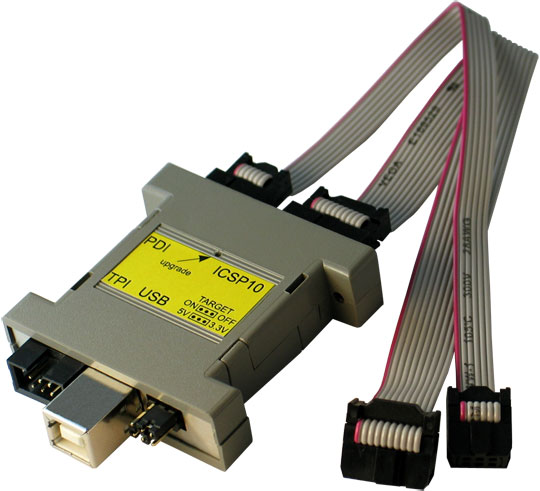
Device comes in a cardboard box with company decals on it. Inside there are 2 ribbon cables: 1x 10way & 1x 6way, and the programmer itself.

As you can see from above they have managed to squeeze the whole thing in a 25way D-sub, what I call "gender-bender" housing (usually cos I find this type of housing is used for swapping sex's of D-Sub's).

There are 4 connections on the device:
  • USB
  • TPI - Atmel's Tiny Programming Interface - for programming ATtiny's
  • PDI - Program & Debug Interface
  • ICSP10 - In Circuit Serial Programming

I'll mostly be focusing on the ICSP port here.

There is also a pin header that allows you to switch power to the target device on or off and either 5V or 3V3.

There are 2 LED's too to show the status of the programmer. 1 orange LED and one bi-colour LED.

After a quick skim read of the manual off the the suppliers website, I realised to use this programmer with AVRDude or the Arduino IDE, I had to reflash the firmware on the programmer.

Manual is: Here

Installing the drivers went well and the firmware re-flash went as per the instructions described.

Bloody Teething Troubles

As with all hardware you except to work out of the box, it didn't, nor was the Manual helpful beyond this. instead of a Green LED coming on, it was now red and the orange LED was on.

First thing was to see if i could program the arduino board through the ISP 6-pin header on the edge of the board.
ISP header shown below the reset button
 Given the ICSP header on the programmer was a 10 way, I assumed it was the other 2 headers, which were 6-way, meant I should use either of them.

With the 6-way cable in the TPI programming port and the other end connected to the Arduino (target), I loaded the Arduino IDE, and made sure that the right programmer was selected:

I then opened the blink sketch and uploaded the sketch like so:

However it didn't work and got the following error:

First thought was that the upgrade went tits up! The manual told me everything about when it should work, but not when it doesn't & the trouble shooting section was quite short!

After some rummaging around on the Arduino forums, I found the error is an indicator that the programmer can't "see" the target board. I've seen warnings on forums that under no circumstances must the -F command be used in the AVRDude command line as the warning suggests! So I didn't bother poking around with that!

After some digging around it transpires that the 10-way ICSP header must use a 10-way to 6-way converter PCB to program ICSP with 6-way headers! Yours from Olimex for £2.00 less P&P.......you got to be F*@KING Kidding me.
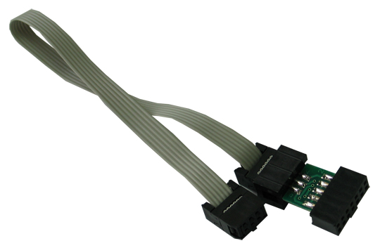
Extras sold separately! Typical!
To make me feel more like a complete Burke, I found out the manual on the SUPPLIERS website was out of date compared to the Manufacturers copy, which gave me more information on what status LED's should be!

Let this be a lesson: RTFM - but make sure its off the Manufacturers website! That way its more likely to be up to date!

So with that fresh information, I was relieved that the LED's were correct (they change status meaning after firmware upgrade), but now knew I had another obstacle in the way! 

No dice Olimex, I ain't forking out more cash! I'll build my own! Dug around for some parts and came up with a homemade solution!

Header Converter
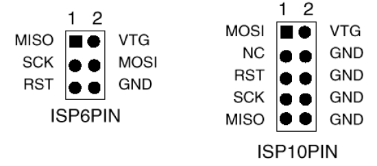


Using the diagram, I basically connected all the identical pins together on the 10-way to the 6-way, like below:
I quickly threw it on a scrap bit of strip board

You can't see it but I placed a dot near the middle pin on the 6-way to signify the place where the keying tab on the cable goes, so as not to connect it up the wrong way round.

Programming the Arduino through the ISCP, Take 2

I STRONGLY ADVISE YOU TO READ THIS SECTION CAREFULLY IF YOUR PLANNING ON DOING THIS, AS THERE ARE SOME VITAL THINGS YOU NEED TO KNOW!

It will be explained later, but when you program the Arduino with the ICSP programmer, it appears to over-write the boot-loader on the micro controller.

THIS MEANS ONCE YOU UPLOAD YOUR PROGRAM VIA ICSP, AND YOU TRY TO UPLOAD WITH YOUR USB CABLE AS STANDARD LATER, IT WILL NOT WORK.

I connected up the Arduino with an LED hanging off pin 13 and the ICSP programmer connected Via my homemade converter, I then tried to load the blink sketch as before, aaaanannnnnnnddddd.......(drum roll):
SUCCESS!!!

It worked! But I had then hit another snag!

I Tired uploading a different sketch to the Arduino and the IDE was acting like it wasn't there.
Typical fault of wrong port selected or not plugged in, or in this case no boot loader!
The only thing I could think of was that I had overwritten the boot-loader when I programmed the Arduino! Using the programmer connected to the same header on the Arduino again. I then proceeded to re-burn the boot-loader to the Arduino:

The programming was successful and managed to use it normally again.

Also if you getting this error on your Arduino, and you have tried ALL other solutions and still nothing, then AND ONLY THEN should you look at re-loading the boot-loader. Don't go spending 17 quid on an ICSP programmer and find out it selected the wrong serial port on the IDE!

So.... what Did I reckon?

Well the Olimex AVR-ICSP-MKII is one 1 of many ICSP programmers out there, and you get what you pay for.

Kudos on design for sticking it in a D-sub housing, but a must try harder on the manual.

Overall I'd say good purchase for beginner, and if you don't want to fork out for a converter then make one yourself like me!

Anyway, I have managed t get my head round on Programming boards with ICSP and the Arduino IDE. This should free up my arduino when it comes to strip boarding and prototyping my future designs

I'll be looking further into ICSP design considerations when prototyping up a project. Will leave that for another entry hopefully.

Laters!

Wednesday, 6 March 2013

Turbo Time! Strip down and Mod of Turbo Gauge

Background

I bought a Greddy Turbo Gauge off ebay a while ago it if in my Landrover. The engine is a 200TDI, which is a 2.5 Litre  Turbo Diesel.


However, When turbo's go, they go VERY badly and are expensive, so this gauge is more to check on how well it is rather than for tuning purposes. A new turbo is £200 for a second hand one and £400 nearly for a new one! A refurb. kit and rebalance is £100, so I'd rather catch it before it goes for a refurb. than when it goes and cough up for a new one! Observing a loss in boost pressure could be an indicator.

Test and Inspect

So i got this gauge a while ago and notice that the guy had cut the back-light wire off on it near to the nub practically. Of what wire I could clip onto, I stuck  12V on it and sweet-fanny-adams, no back-light!

I then got a mate to check the gauge worked, whilst I blew into the pipe inlet, needle moved when I belw so at least it's primary function worked!

I extended the wires on the back-light first, as this was an easy job, and plus I need to reference which one was positive.


Disassemble!

To quote a certain Mad Aussie Bloke (+EEVblog) :
"Don't turn it on! TAKE IT APART!"
I began to dismantle:
I undid the nut holding the inlet on the back of the turbo, in hoping to loosen something up. No luck! All I succeeded in was to knack up the needles default position. So this meant I had to cut off the crimped on collar holding the front screen in place.....I'll have to come back and think of a way to put that on later.

With the glass out and the nut on the inlet off, I slide the gauge face out of the casing, Inside was a circuit card with 2 blown filament bulbs soldered onto it (why, why would you solder a device that you know will blow and needs servicing to a PCB!) and on the back of the gauge face, what looked like the insides of a grandfather clock!
Old Skool Brown and copper PCB!

WHY! WHY, solder these on?! Use a F*@king socket!

Pretty Primitive when you look at it!

Inner Workings

After a closer inspection, I managed to work it out.

The thick bent piece of copper is a hollow and is connected to the inlet by a small piece of copper pipe. One end of the bent copper is soldered shut. The closed end of the copper is connected to an arm, the other end of that arm has a toothed rack, that moves a toothed spindle. The spindle is connected to the needle on the front of the gauge and a coiled spring, so the needle can return to its rest state.

When air pressure is applied to the inlet, it inflates the bent copper pipe slightly, this cause the bent copper to expand by increasing its radius (basically trying to straighten itself out!). This pulls on the arm which moves the needle.

There are a lot of small movements involved, that are scaled up to big movements (needle). It could be said that this is a mechanical amplifier!

I managed to reset the rest position of the needle by squeezing the the bend copper pipe slightly to run the rack off the spindle allowing the needle to move freely. Then just resetting the needle so that when the rack ran back onto the spindle, so that it rested as near the 0 mark as possible.

Modifying the PCB 

So the first thing was that stupid filament bulbs come off, with a hot soldering iron:

I had a couple of spare white LED's lying around at home. These will do to replace the bulbs.

Now a few calculations to work out the current limiting resistor:

I got the Vf & If from hooking one of the LED's up to a PSU with a low current Trip and carefully cranked up the voltage with the fine adjust:

So why have I hooked up the LED's in series? Well given that my input voltage is much greater than Vf of each LED, I can do it this way and only have to use 1 resistor.

"But you could do it in parallel, and not hack up the PCB as much!"
Yeh, but that's the wrong way of driving an LED, working below shows why:

Both solutions pull twice the current. Yeh I know its gonna be supplied by the landy's battery and alternator, but that's no excuse to be inefficient! The top solution is not good as I know these 2 LED's are not exactly from the same silicon die! Hence it can't be ensured that each LED will pull 10mA each, and as such their forward voltages will "fight" each other.

If you wan to drive more than one LED at a different current, then the second solution is more suitable.

The top Solution should NEVER REALLY be used!

With components sourced, I modified the LED's so they could be soldered on at the same height as the bulbs:

After some track cutting on and soldering of a few link wires, I got the PCB how I wanted it:

Testing

I set the Benchtop PSU as follows:
So this is basically simulated running off the battery, I set the current trip to the max current limit the LED's can carry, so I don't blow them in the event of a fault.I know they can carry more, but I designed them for 10mA, so more than 20mA, I know somethings VERY wrong!

Flicked power on a VIOLA! Not too bad!

And current consumption is near as damn it spot on to calculations!

So, cranked up the voltage to simulate the alternator running.

Flicked power on. Hardly much difference......

I did expect a current rise of this proportion, so all is as I expected.

So all in all, I'd say that was working properly!

Re-assemble

I popped the PCB back in its place:

Popped the dial back on and bolted the inlet to the back of the case. I then hooked her up for a showcase!
OHHH! Pretty!
You'll notice the bright spots on the dial, this means the LED's are too close to the dial, not the worst thing that could have happened!

That's good! But Have you knacked it by taking it apart?

Well, I  looked at the needle in the mirror whilst I blew into the inlet. The needle moved into the positive pressure range, whether by the right amount I don't know ( I blew to about the 0.4kg/cm mark). If this is wrong then I would think the spring needs adjusting.

The main thing that's a concern is how I'll get the glass cover back on now the collar is mangled! Super glue and a G-clamp is looking a likely solution.

Once I've sorted that, then its ready to mount on the centre dash console with another project I have in the pipeline....watch this space!

Wednesday, 20 February 2013

Tron's online!

Yup, this is Me!

...with my head in outlet of a jet engine. But this engine is gonna be bolted to Bloodhound SSC! So that makes my gormless expression ok....right?

So I thought it was about time I got myself a blog, to document all my project and basically share them online, and hopefully part some wisdom to those looking for help on similar projects.

I'm an electronic engineer, budding mechanic, proud father & general tinkerer. My tinkering goes as far back as deconstructing the family toilet cistern.... at the age of 4! Fortunately, my parents stopped me before I caused the house to be flooded. But I was really curious as to how it worked!

Since then, I've left a lot of dismantled things in my wake, most of them went back together again ok....

What I'm doing now.....

Since leaving Uni. with my electronics degree, I've done a lot of jobs:
  • Fixed welding equipment
  • Been a Lab Technician for a computer science department
  • Technician for a company that builds underwater R.O.V's and Submarines
  • Operator and Technician for a Ferris Wheel (like London eye, only smaller. Nothing like swaying 80ft in the air at 6am, counting split pins on each spoke of the wheel!)
Right now I'm working on some cool stuff to do with protein and veterinary allergy analysers.

My Electronics skills are somewhat geared toward, analog and linear circuits. I am REALLY experienced with EAGLE and as part of my job, I design PCB's to exacting standards, so I know my way around a circuit board!

About a year ago, I learnt about the Arduino  platform. My Micro-controller skills at the time were, well....crap. I could read C-code, but not very well.

After buying my first Arduino starter kit and a copy of Getting Started with Arduino, I was bang up to speed and really impressed with how versatile the platform was! It opened up a new range of projects that I had stuck in my head, but had no way of bringing it to life.

By looking at projects on hack-a-day,  I got the inspiration to get my arse into gear, AND BUILD SOMETHING!

So why has it taken me nearly a year to get my first project here....

Well in June 2012, my son Hugo was born, and since then I've been concentrating looking after him! Both him and my girlfriend Georgina, are the the best things in my life.


What else am I up to.....

As mentioned, I am a budding mechanic. During a spell of brief depression, I remembered my mate was building a trails off-road vehicle. I am a keen petrol head and pretty good at wiring so offered my services to help.

In turn for electrical know-how, I was taught the ins and outs of repairing and maintaining land rovers and how to weld properly.

Since then I got hooked so bought my own Trails vehicle! A bit of wiring, a few lights added, and some wing-mirrors bolted on, it was on the road in no time....and then back off it!
I'll be posting another blog about the vehicles I helped build at a later date.

Well that me roughly in a nutshell. I hope to update regularly!