Showing posts with label arduino. Show all posts

Tuesday, 7 July 2015

Arduino Uno IO Expander

Well I've moved house! Finally Have a garage to do my work in! But at the moment its full of boxes and crap! give it a weekend's work and I'll have the space freed up!

In the mean time: I've come up with a simple and effective little project on expanding the IO on an Adruino Uno.

The Uno

The Uno should be a fairly familiar board if your into electronics. Its one of the first boards released by the Arduino company: early versions had D-sub interfaces, migrating to USB and eventually to the current Rev 3 boards and some SMD editions. 
Early Arduino Uno - Wikipedia
Later Versions had USB
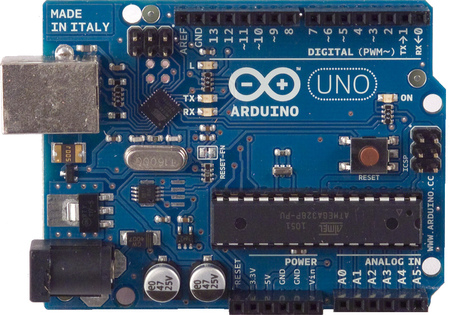
The Rev 2 (Version I own) notice the interface chip next to TxRx LED's is offset 45degrees
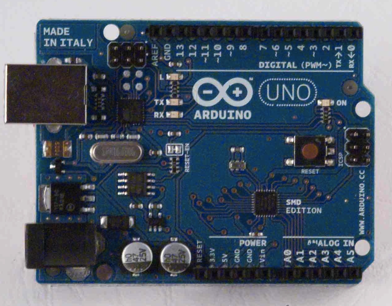
SMD Edition
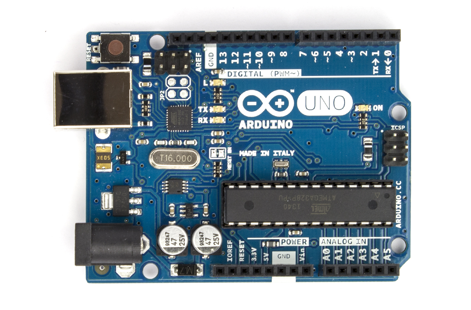
The Rev 3. Notice the position of the reset button
There are also loads of Rip-off versions, nothing wrong with them, they may be cheaper, but I prefer going with the real deal.

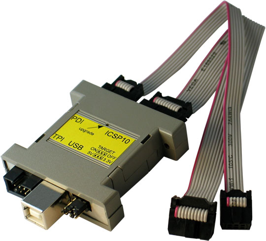
I have the Rev 2, based around the Atmel ATMEGA328P: 28-pin DIP, 8-bit micro controller. Beauty of this version is if the chip blows, you can buy a new one either programmed or un-programmed and swap it out. If its un-programmed, you will need to program a bootloader to it through the ISCP header: Olimex Programmer Review

However, on mine, A0 is busted. So in the meantime until I get another chip ordered, I thought I'd figure out a way of how to get more out of the other analog inputs.

A simple way of doing this is to use an analogue switch IC. You can use a multiplexer, but analogue switches can usually work both ways, whereas multiplexer & demultiplexers can only usually work in one way. Also make sure you have an analogue switch or mux/demux for analogue applications and, digital ones won't work as required!

As mention above, analogue switches work both ways, so you can have one input accepting a number of sensors, for example, or have 4 inputs from 1 sensor. Also they can be good for auto-ranging circuits or gain adjustments circuits, by clicking in more or less feedback resistance.

The Setup & Code

I'm basing this around a DG409. Its an array of analog switches in various configurations. The 409 is 2 sets of Single Pole, Quad Throw (SP4T) switches. Each position is selected by the address pins A0 & A1. Its all there in the datasheet.

With this I was able to connect up a number of sensors to one bank of switches:
  • S1A: pull-down switch
  • S2A: A voltage divider (div. 10) from a higher voltage supply
  • S3A: An LDR
  • S4A: a Pot
I then connected the pin DA to the analog input and some digital pins to the address pins A0 & A1 of the DG409. The full setup is shown here:


I'm using an interrupt switch on pin-2 so I can cycle through the different sensors at any time.

The COM or output of the DG409 (white wire) is connected to the A1 analogue input of the UNO. This now essentially has 4 inputs now on one analogue input! All i have to do is program a way to change the address each time I press the interrupt switch.

I managed to punch out some code in under 15 mins:


So a breakdown of the code:

  • In the setup I have declared some pins as outputs, set pin 2 as the pin to activate the ISR (Interrupt service routine - https://www.arduino.cc/en/Reference/attachInterrupt), and started the serial monitor going.
  • I then declare the integer sens to be used to select the address of which switch to select on the DG409
  • The loop basically reads the analogue input A1 and prints it on the serial monitor whilst also printing which sensor its looking at. it does this every 500ms using delay(500);
  • The ISR is where most of the work is:
    • 1st it checks if the integer sens is less than 3, if it is then it can be incremented
      • if it is not less than 3, it resets it back to 0 again.
    • it then checks the value of sens using a switch-case and sets the outputs 8 & 9 to the appropriate logic, and therefore address for the DG409 - truth table of addressing can be seen in datasheet.
So in my example, sens: 0 = pulldown switch (addr: 00), 1 = divide by 10 circuit connected to a 30V variable supply (addr: 01), 2 = LDR (addr: 10), 3 = pot (addr: 11).

Results

Uploaded the sketch and opened the serial terminal:
Pressed the pull down switch for about 5 seconds

Adjusted the 30V supply from 30V down to 0V
 So in this case at 30V my full scale was 574.;
574/1023 x 5V = 2.8V;
2.8 x 10 = 28V, well I did have the fine adjustment turned down (its an old supply) so I'll take that as correct!
The LDR output. Here I was moving my hand over the LDR

POT adjustment, rotating to both ends.
It all works as expected. So that's a win in my books.

Conclusions

Well it works, its pretty simple to do and you can get a lot more I/O for very little extra cost and effort.

However there are limitations:
  • Time frame & speed limits - if the sensors require fast monitoring, and you have 4 of them, then you have to switch between them all really quickly.
    •  This takes time and to get an accurate reading at a given time frame (say 1uSec) and the time it takes to go through them all takes 10uSec, then your going to loose some data on that sensor whilst reading the other sensors - so bear this in mind. 
    • Make sure your sensors a slow when compared to the speed of the UNO (or whatever board your using) or utilise some sort of averaging in your programming.
  • Giving up some digital IO - ok its only 2 pins! But if your applications uses lots of digital signals, then you might have to work out some sort of addressing or serial interface to your analogue switch, or find a switch with some serial interface.
Those are the only 2 major ones I can think of.

Changes?

So why did I use the ISR: well because between each reading I was waiting 500ms, which is quite a long time, so I needed to interrupt right in the middle of a delay function, rather than wait 500ms to check a change in state of the sensor select button.

I could have just collected the data from all the sensors and spat them at the serial terminal in one go, that too would have been quicker.

I did originally use some port manipulation to set the address of the switch. but that meant a lot of pins weren't being used and would look somewhat intimidating to noobs. Have to be efficient yet friendly. Though if any noobs are reading this then: seriously, click on the link and go tinker, its a function worth knowing.

Anyway, this should help if you are looking to get more I/O out of your UNO, or any dev. platform. Go have fun!

Tuesday, 19 August 2014

MIG welder rebuild update and Welding Practice (on a budget!)

Update


So I managed to get a screen on the Ardu-weld (which I have now decided to call Ardu-MIG) doesn't look too bad and can update the info on the display on the fly when adjusting feed speed and gas delay. I am implementing a latch mode and possibly a stitch mode, but will see how that goes.

Welding Practice

Even though I could wax-lyrical about how welders work, I can't weld for jack-shit! This is apparent in the fact that I have tried to weld the steering guard back on big blue 3 times and 3 times I've driven back from a trail with it in the passenger seat! Still better than it catching a lift on an AA truck with track rod in your hand!

I thought I'd look up welding tutorials on YouTube and came across this guy: +ChuckE2009 
The tutorials are a little long winded, but its necessary as there are lots of factors to consider when stick welding (drag angle, angle to the work, electrode types). He does seem to know his subject well, young enough to remember, old enough to be experienced, good balance!

Budget!

I am basically learning how to weld with my means here! I am skint, have limited space and am willing to learn, so as you'd expect, my kit is not the best, nor do I have the facilities so I have to make it do!

So after watching the playlist, I thought I'd have a go, and managed to scrounge some scrap from a neighbor. bit of a buff up with angle grinder to remove rust and it was good enough.

I already had a stick welder, which I manage to get for about £40 just a basic thing! It has seen better days, the electrode holder was on its last legs but the cabling was in good nick and the cooling fan did still work, so it was mostly cosmetic.

I bagged some electrodes at the local farmers auction! Probably 10kg of a mix bag for about £20! Bargain! Their quality couldn't be call on, as for all I know they could have been stored in a damp area, but they looked good, no signs of dampness!
Left to right: 2.5mm (unknown type), ESAB 30.25(?) 3.25mm, 6013 3.25mm, Stainless Steel 3.25mm
So for practicing I used the 6013 3.25mm as it suited the metal thickness I was using and was the only one I could identify from the welding tutorials!

So out in the Garden (after the kids gone to bed) I set-up my work space:
The reason I had to work outside the shed was:

  1. No welding within 3m of flammable materials - shed is full of bottles of various petro-chemical fluids from servicing vehicles, oh yeh and AND ITS A WOODEN SHED!
  2. Not enough room
  3. Ventilation - you need  a lot of ventilation when stick welding, the fumes given off are not nice!
I am aware that I am welding on a wooden board, but the the work is performed upon a large piece of scrap metal which make a good heat sink and only mildly scorched the board. As an extra safety addition I had a fire extinguisher on standby!

I didn't have a chipping/slag hammer, but the back end of a claw hammer did the trick. I do have a welders mask  which I bought new for about £15, just a flip down thing with a flipable lense. I also had:
  • a wire brush, to clear away loose slag
  • an angle grinder to cut and clean metal
  • some ear defenders - for when I'm using the angle grinder
  • some tough garden gloves I use when using the chainsaw
  • a piece of box section - I used this to rest on

Sparks Fly!

I set the amperage as per the ratings on the side of the box of sticks and the silk screen on the welder:

I measured the bare end of the electrode by eye with a steel ruler and came out to be about 3mm - so I took the size up for 3.25mm and wound the dial on the front till the pointer on the scale came to 3.25mm or about 115A

First off I decided to put a pad of beads down:
This was to get a feel of things, practice putting and arc down and generally observe if I was moving too slow or fast and if my arc was too long or short. As the pad got warmer I back the current off a bit by about a few amps, I couldn't tell really as there wasn't any scale to go by!

I decided that I was going too fast for the first 3 beads so by the 6th bead I was happy that I'd got my drag speed dialed in. Drag angle appeared to be ok and arc length was bang on.

After a bit of practice I then moved onto a fillet weld and then a triple pass fillet weld. I first tacked up 2 pieces of metal so one was perpendicular to the other:
Then began to weld my single pass fillet weld on one side:
For a first try its not too bad! I seemed to be moving too fast at the start, not enough cut in the middle and improved a bit toward the end.

I then did a multi-pass on the opposite side:
Hmmmm - keep practicing I guess! The light at this point was fading and I was getting thristy - dehydration is not a good thing when trying to learn new things!

Lessons Taken

Well I am better than before and I have learnt quite a bit more than I did, however there are still more techniques to learn (lap weld, open root, vertical up and overhead)

Also my kit did not fair well! The electrode got REALLY hot by the last weld! after taking it apart I found the contact between the cable and holder was tarnished and the grip had melted!! I took it off and ordered a new one for a a Murex stick welder - rated at 400A and much better contact material with brass cable clamping!

My gloves where not thick enough and found out they had holes! not good! ok if your operating a chainsaw, but not for welding! So I order a set of good welders gloves. The mask faired well too!
Old glove to new gloves; new electrode to old and mask
 Also, and I am a burk for doing this, I thought I wouldn't be long and welded in just a t-shirt! Bad idea, I got colossal sun-burn on me left arm! Welding arc's emit a fuck-ton of UV radiation! Please make sure you have a long sleeved top on if your doing this! Ideally one that's old! either that or wear sun-screen!

More practicing will follow soon and maybe another update on the Ardu-MIG!

If you have any comments or pointers on my welding, feel free do so, I'd be much appreciated! And may thanks to +ChuckE2009, keep up with the videos dude! Helping a lot!


Thursday, 31 July 2014

MIG Welder rebuild update

If you don't know already, I've been busy.....bouncing baby #2 arrived in June! Her name is Ferne. All is well with her and muumy!

So plodding on with this MIG welder (kindly donated by +Jezzmund Tutu's dad. Cheers Mark!), I managed to knock a milestone down: I have managed to develop a working system on the Arduino, with a development board I knocked up!

What I'm Aiming for

I basically want to try and run this, knackered, beat-up, SIP Ideal 180 Mig Welder, by replacing the electronics (as shown ) with my own, more modern and compact system, based around the same system as the Arduino (Atmel ATMEGA328P), with ability to upload an Arduino boot-loader and then use a serial cable to upload programs.

Electronics as it stands are shot, keeps blowing the fuse to the board, I believe there is a short on the rectifier for the motor control circuit. I never liked the way these things worked, so more the reason to design my own!
Proper old-skool electronics! who needs micro controllers!

All this will be stripped out, but am leaving the connections and wires to solder to the new board

Plenty of functions for a MIG, including latch trigger mode and stitch mode with duty adjustments. I'll be recycling the pots and rotary switches.

Basically the same way as done on Arduino, Stripped down and instead of a USB to serial circuit on board, use a USB-Serial Cable, available from most electronics hardware suppliers. Similar to what's done here: Nanino.

I want it to have all the basic functions of a MIG welder: Gas delay, Wire Feed control, Wire-Inch. The welder is a Conventional type, which means it has a HUGE, tapped, step down transformer, and a selector switch on the front to adjust the welding voltage (CV welding explained Here - Wikipedia on welding power supplies). As such, I don't need to worry about controlling the welding current and voltage from the electronics, just the gas and wire control.
Pretty beat up! Confident its just cosmetic! The number in the model name usually indicates its max current.

Left to Right: Voltage adjustment, "EARTH" clamp connection MIG/Spot welder selector, 3-Phase connector (dunno if its in or out?)
I did think about having a weld mode selector for stitch mode, stitch period on & off and latching trigger but I thought to start simple and then fit mode selections later.

Dev. Platform

Schematic - NB trigger button is separate on breadboard
Setup

The board is nothing special. Just a couple of relays with LED's. Relays are driven off 5V (as specified) by some transistors which in turn are driven off the Adrunio. Screw terminals allow easy fitting/removal of the wires to and from the Arudino and also from the bread board.

The  Inch button is located on the board and the trigger button is on the bread board with a bit of de-bouncing. I found a small motor so I could test drive the motor circuit I proposed to use. The motor so small and light that the solid core wires I soldered to it can hold it in the air!

I used 2 Trim-pots as gas delay and motor control. The motor driver circuit is quite simple too: the MOSFET (Q4) is constantly driven by a PWM signal from the Arduino. The relay (RL3) in its Normally Close position, shorts the motor out through a very low value resistor (R7). When the relay is energised, the pole is switched to the 12V supply and Q4 has some power to drive the motor with. Simple and effective.

Some Theory

R7 essentially holds the motor. If you tried to turn it by hand, it won't budge as all the current generated by the motor tries to flow through R7, essentially a short circuit. 

You ever tried to generate a voltage across a short circuit? Its bloody hard! 

If R7 were 1K for example, it would allow the motor to be turned by hand a little and the current generated from the  motor would give rise to a small voltage across it (ohms law).

So in the situation where the motor is running and then you remove the power, the motor will slow down over a short period of time. This is not desirable if its feeding your wire for welding as it could get stuck to the work! you want it to stop instantly!

So by shorting the motor through the high wattage, small value resistor, all the current generated in the field of the motor windings from the momentum of turning a big spool of wire gets dissipated as heat in the resistor and the motor will stop a damn-sight quicker! exactly like the brakes on a car!

I've seen similar things done with Triacs and long pieces of track whilst repairing boards from MIG welders. They are prone to blowing the tracks and the braking Triac alot! So if your MIG welders does not stop feeding wire when it should, that's the problem!

Arudino Sketch

/*
Ardu-weld - Arduino based welder control board
Author: Tronicus
Date: 13-May-2014
Ver: 1.0
web: tron9000.blogspot.com
*/

//files to include
#include <Wire.h>
#include <stdlib.h>

//definitions & declarations
#define in_TRIG 2  //trigger pin
#define out_WS 3  //Motor speed control pin
#define out_GAS 7  //Gas relay control pin
#define out_CON 8  //Contactor relay control pin
#define out_BRK 4  //Motor brake relay control pin
#define in_WF 12  //Wire Feed button input pin
#define in_DIR 5  //Wire feed direction control input - later version of development
#define out_DIR 6  //Wire feed control output - later version of development

//Variables
int WS_MIN = 20;  //Minimum wire speed
int WS_MAX = 255;  //Maximum wire speed
int GDEL_MIN = 10;  //Minimum gas delay time
int GDEL_MAX = 1000;  //Maximum Gas Delay time
boolean welding = false;  //flag to indicate has been or finished welding

//*********************************************Main Program*******************************************//

//setup
void setup() 
{
  pinMode(out_WS, OUTPUT);
  pinMode(in_TRIG, INPUT);
  pinMode(out_GAS, OUTPUT);
  pinMode(out_CON, OUTPUT);
  pinMode(out_BRK, OUTPUT);
  pinMode(in_WF, INPUT);
  pinMode(13, OUTPUT);  //LED Alive pin
  digitalWrite(13, LOW);
  //Serial.begin(9600);
}

void loop() 
{ 
  while(digitalRead(in_WF) == LOW){inch();}  //check to see if Inch button is pressed
  while(digitalRead(in_TRIG) == LOW){weld();} //check to start welding
  if(welding == true){dis_weld();} //if you have been welding: disengage
}

//******************************************Welder control******************************//
/*
Code for controlling the welder (Wire feed, contactor, gas solenoid, trigger type) goes here
*/
void weld()  //starts welding welding
{ 
  welding = true;  //now/was welding
  digitalWrite(13, HIGH);
  digitalWrite(out_GAS, HIGH);  //turn gas on
  //Serial.println("GAS ON!");  //uncomment as neccesary
  digitalWrite(out_CON, HIGH);  //close contactor
  //Serial.println(welding);  //uncomment as neccesary
  feed_wire();  //feed wire
}

void inch()  //feeds the wire
{
  while(digitalRead(in_WF) == LOW)
  {
    feed_wire();
  }
  digitalWrite(out_BRK, LOW);  //turn on brake
}

void feed_wire()  //function that feeds wire whilst allowing speed adjustment at same time
{
 digitalWrite(out_BRK, HIGH);  //Release Brake on motor
 analogWrite(out_WS, map(analogRead(0), 0, 1023, WS_MIN, WS_MAX));  //set the output speed of feed motor
}

void dis_weld()  //stop welding and finish with gas
{
  int del = map(analogRead(1), 0, 1023, GDEL_MIN, GDEL_MAX);
  boolean FLG1 = true;
  while(del > 0)
  {
    while(FLG1 == true)
    {
    digitalWrite(out_CON, LOW);  //turn off current
    digitalWrite(out_BRK, LOW);  //apply brake to motor
    FLG1 = false;  //make flag false so this isn't done again
    }
    delay(1);  //delay 1 ms
    if(digitalRead(in_TRIG) == LOW)  //read and check that trigger has not been pressed
      {
        del = 0;
        weld();  //if so weld
      }
    //Serial.println(del);
    del--;  //decrease del
  }
  digitalWrite(out_GAS, LOW);
  welding = false;
  digitalWrite(13, LOW);
}

Breakdown of Program

so in the main loop(), I'm constantly checking the trigger and inch switches for a change in state and then calling the appropriate function when one of those switches are pressed.

When the inch button is pressed it just calls the function to turn on the wire feed motor at the speed set from the analog input, mapped against the defined max and min wire speed, this only happens while the inch button is pressed. once the inch button is release it engages the brake for the motor.

when the trigger switch is press it calls the welding function: this function first sets a flag (in the form of a Boolean variable) to acknowledge that welding has/is happening/happened. It then turns on the gas solenoid output and then the contactor (which puts power to the lance for welding) and then starts to feed the wire at the mapped speed from the analog input. It does this till the trigger is released.

Once the trigger is release, it returns to the Loop(). It then checks that the welding flag has been set, if it has then it must start the welding disengage function. 

This function basically reads in the value off the second analog input to determine how long it needs to leave the gas on for, sets another flag to indicate it has turned off the contactor and apply the wire feed brake, and then checks at 1ms intervals if the trigger has been pressed whilst the gas is left on.

If the trigger has not been pressed during this interval, it decrease the integer: del. When del = 0, it turns the gas off and set the welding flag to false and returns to the loop(). If the trigger has been pressed, it clears the timer variable (int del) and returns to the welding function.

And the results can be seen for themselves:

As it can be seen, I Press the inch button and only the motor turns. I press the trigger and the Gas (green LED), contact (red LED) and the blue LED (sequence indicator, tells me when its stopped doing things) come one and the motor turns.

When the trigger is released the gas LED stays on for a while longer. I adjust the Gas pot and the gas on interval is now a lot shorter (practically 0).

I then adjust the motor speed pot from full, to half way and then minimum, and the motor speed responds accordingly. Notice that the motor recoils a little, that's the brake circuit kicking in!

Sorry I couldn't show the speed change on the fly, but I had to hold the camera!

Expansions and Extra features

So like I said before I could have included and stitch function and a latch function like the original, I might yet include a latch function.

I was also thinking of including a motor direction switch for inching only, so you can spool the wire back a bit if required.

I would really like to add one of the LVK204-25 LCD screens on it to display current and power. I have a few analog and digital inputs left and it'd be rude not to use them!

Problem with measuring current is I need a shunt capable of taking high current (most likely up to 180A), which in this case would be a brass bar with enough metal shaved off to give the right resistance. Seen them before, will have a look around. Also with measuring shunted currents and voltages up to 5x higher than the mirco-controllers supply voltage is isolation. I've seen monitoring circuits in welders go really badly when things let go!

Anyway, food for thought, until next time.

Friday, 24 January 2014

"Trash" find screens - testing

About a few months ago, I caught one of my work colleagues throwing out some parts from a project long since mothballed.

"They're all going!" - nod from my colleague; I told him to put them to one side, had a chat to higher ups to make sure I could "acquire" them: "If you can pull em, you can have em! Bin wagons due in 3 days" - managed to pull out roughly 30 screens out of these dud units along with more stepper motors than I knew what to do with and about 30 V-Drives (that's for later).

About half the stepper motors went to a mate who was building a 3D printer - I think he's set for about 8 printers!! But as a thank you, he bought me a Erbauer grinder + blades (SWEET!), which I needed to do some work on the landy - which reminds me, I should post some work I've done on that thing on here!

So did any of these screens work? Some were still in packaging, some I'd removed from fittings but didn't even know if they actually would power on, so I did some digging:

The Screen

Its a 20 Character by 4 line LCD which is backlit in blue and with white text. That's all I knew about it when I first looked at one. After a google: JACKPOT - Matrix Orbital - VK204-25

Turns out it had more connectivity than any other LCD I'd seen: I2C, RS232, TTL, USB, RS422 & Dallas 1-wire (new to me anyway!). I was doubtful about its USB capabilities as I could not see a USB port on it, but it had footprints for one.

It also has an input for a keypad and a set of 6 general purpose outputs.

Physically, it is a 2 boarded device; by that i mean it has one board that appears to handle the communications protocols the user selects and the board with the screen fitted, which I assume is a standard LCD based around a Hitachi HD44780 LCD controller. I assumed this from the interconnecting header between the 2 boards: its pretty similar to most LCD's out there and seems to be a standard that many manufacturers seem to adopt - but from the data sheets and info I can't verify that.

I suppose by that observation, and if you were deft enough, you could pull the LCD Board away from the interface board, if you just wanted the LCD on its own.

Getting Started

When I had pulled them out of their units they were connected by a 4-way molex KK header, which turned out to be the TTL & I2C port, with power pins. I had heard of I2C and have designed systems for I2C devices, but never actually got to grips with it - this opened a perfect opportunity to pull out the Arduino and get started.

Fortunately; Matrix Orbital supply an some demo code designed for  the Arduino environment:
  • Arduino I2C demo - it's technically not for this screen, though if you pick it apart, it works
  • LVK204-25 serial demo - opens download from googlecode in .ino format, no documentation unfortunately but will allow you to communicate to the device if its set in RS232 mode
I whittled up some pull-ups onto a bread board and linked the connections for the I2C bus via them to the Arduino:
such a tidy desk....its not like that now!


I then pulled the Demo sketch apart and managed to get it display text, as above. Now that I could get it working, I decided to expand the setup so I could test them all.

Test Development

To ensure all aspects of hardware were functional, I decided on a set of tests:
  • Make sure the backlight works
  • make sure that there aren't any dead pixels
  • test to make sure that the contrast is good
  • make sure that it can display test legibly -  and not garbage/corrupted
  • test that the General Purpose Outputs are working
This I thought was enough to go on to ensure that they weren't buggered. I thought about testing the keypad input, but I thought that its mostly a device based on outputs and not to bother.

I decided that each test would loop and then press a button to confirm that test had passed and then move onto the next test. The test takes a little longer then if it went though each test automatically, but I wanted to do something with interrupts to prove to myself I could do it.

After some tinkering with the contrast functions, I decided that I could perform a dead pixel test by ramping the contrast up to full and look for empty spaces in each segment.

So I came up with this setup:
Here's a picture of the back of the LCD to show where all the connections went:
Connections to LCD - 4-pin KK is comms & power, 6-way header is GPO. D-sub 9way can be seen for RS232/RS422
The LED's are 5V rated, hence why there is no current limiting resistor on them. I added a resistor & cap to the switch as while testing the code, there was alot of debounce on the interrupt, causing it to skip tests.

After a few trials I settled on this code:


I'm not sure if i should have included the Wire.h library (is it included by default in the arduino IDE?). Anayway; you power it up, after the screen has been setup by running the function LCDSetup(), the while loop runs the the SwitchCase to check the test number it should do. Each time the interrupt button is pressed; the integer: Test is increased by 1, so long as it doesn't already =4, as there are 4 test and going beyond that may cause it to take a hissy-fit!

With each case, is a function to perform a test; within them are the relivant functions to send values to the screen for Backlight brightness, contrast & so forth by using Wire.beginTransmission to the I2C address specified in the beginning of the code (#define I2C_address 0x28, as specified in the manual)

And here's how it worked:
Backlight test

Contrast/dead pixel test

Alpha-numeric test

The Welcome screen

Toggling GPO

The setup


Issues

One minor issue was that the interrupt didn't take affect instantly, it only kicked in till the test had ended. Its not that bad.

One other thing I found: whilst testing some screens that were already packaged; the would power on but only displayed the default screen. After a quick read of the manual: i found that you have to solder some jumpers onto the board to enable the mode you require:
Notice the solder bridges made in the area marked I2C - this means its in I2C mode

Here: there are 3 0R links in the area marked RS232, just under the silkscreen text LVK204-25 - this means its in RS232 mode.
Also you will notice there are some track going from the jumper pads for the RS422 mode, leading to and un-populated IC footprint: U8. This also means that RS422 is not likely to be featured on this model of screen.

I'd like to point out at this point that this is why you RTFM!
I found that un-soldering the links from RS232 and bridging over the pads in the I2C area, I managed to get the screen to work on the test bed. So by default, they are shipped in RS232 Mode.

Outcome

I'm now using this test bed to verify the screens I have work. This is cos I am selling them! yup, they're going to be up on ebay! once I've tested them all, I'll be posting a link up on this blog if your interested in buying one.

They make a great tutorial tool and an excellent display for any project. Plus can expand the outputs of a micro controller project if needed (say you were making a project with an 8-pin ATiny?)

I suppose I learnt a bit more about functions, switch/case, more about using interrupts and a I know more about communicating with device than I did before. At least from this end of the device!

I must admit my code is very messy and thrown about, I really need to hone my skills getting the functions onto one sketch and reference it in the main sketch - something I could do next.

I will be saving a few screens for myself. I would definitely get one - they are quiet a useful little thing, even as a beginner you can learn a lot about I2C.

Feel free to pull my code apart & watch this space for the ebay link if your interested

Tuesday, 2 April 2013

Olimex AVR Programmer

A bit of a Heads up!

Whilst messing around with this programmer, I found you can accidentally over-write the boot-loader on the Arduino by uploading your program through the ICSP header!

SO YOU HAVE BEEN WARNED IF YOU PLANNING ON DOING THIS! I DID NOT BREAK YOUR ARDUINO! It just needs the boot-loader re-loading! See below

Bit of Background

So with some up and coming Arduino project coming to a close, I want them to become stand alone widgets, where they can be soldered onto a strip board and utilise a controller of their own, like the ATtiny range of micro controllers.

ATtiny85 - Small, dip-8 package, really useful
You can program chips on breadboards using the Ardunino as a ICSP (In Circuit Serial Programmer: ICSP wiki definition)

I found this Link: Programming an ATtiny with arduino, a while back and managed to program an ATtiny85V with the Blink sketch in the Arduino IDE, which as proof enough that it could be done for me. Big thanks to those guys at High Low Tech, MIT!

However, this kinda makes your Arduino tied up doing tasks that something else can do. So I purchased an Olimex AVR-ISP-MKII.

Unpacking and Setup

Device comes in a cardboard box with company decals on it. Inside there are 2 ribbon cables: 1x 10way & 1x 6way, and the programmer itself.

As you can see from above they have managed to squeeze the whole thing in a 25way D-sub, what I call "gender-bender" housing (usually cos I find this type of housing is used for swapping sex's of D-Sub's).

There are 4 connections on the device:
  • USB
  • TPI - Atmel's Tiny Programming Interface - for programming ATtiny's
  • PDI - Program & Debug Interface
  • ICSP10 - In Circuit Serial Programming

I'll mostly be focusing on the ICSP port here.

There is also a pin header that allows you to switch power to the target device on or off and either 5V or 3V3.

There are 2 LED's too to show the status of the programmer. 1 orange LED and one bi-colour LED.

After a quick skim read of the manual off the the suppliers website, I realised to use this programmer with AVRDude or the Arduino IDE, I had to reflash the firmware on the programmer.

Manual is: Here

Installing the drivers went well and the firmware re-flash went as per the instructions described.

Bloody Teething Troubles

As with all hardware you except to work out of the box, it didn't, nor was the Manual helpful beyond this. instead of a Green LED coming on, it was now red and the orange LED was on.

First thing was to see if i could program the arduino board through the ISP 6-pin header on the edge of the board.
ISP header shown below the reset button
 Given the ICSP header on the programmer was a 10 way, I assumed it was the other 2 headers, which were 6-way, meant I should use either of them.

With the 6-way cable in the TPI programming port and the other end connected to the Arduino (target), I loaded the Arduino IDE, and made sure that the right programmer was selected:

I then opened the blink sketch and uploaded the sketch like so:

However it didn't work and got the following error:

First thought was that the upgrade went tits up! The manual told me everything about when it should work, but not when it doesn't & the trouble shooting section was quite short!

After some rummaging around on the Arduino forums, I found the error is an indicator that the programmer can't "see" the target board. I've seen warnings on forums that under no circumstances must the -F command be used in the AVRDude command line as the warning suggests! So I didn't bother poking around with that!

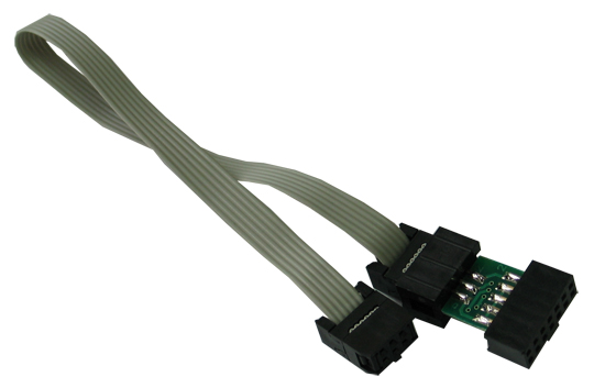
After some digging around it transpires that the 10-way ICSP header must use a 10-way to 6-way converter PCB to program ICSP with 6-way headers! Yours from Olimex for £2.00 less P&P.......you got to be F*@KING Kidding me.
Extras sold separately! Typical!
To make me feel more like a complete Burke, I found out the manual on the SUPPLIERS website was out of date compared to the Manufacturers copy, which gave me more information on what status LED's should be!

Let this be a lesson: RTFM - but make sure its off the Manufacturers website! That way its more likely to be up to date!

So with that fresh information, I was relieved that the LED's were correct (they change status meaning after firmware upgrade), but now knew I had another obstacle in the way! 

No dice Olimex, I ain't forking out more cash! I'll build my own! Dug around for some parts and came up with a homemade solution!

Header Converter


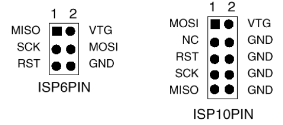
Using the diagram, I basically connected all the identical pins together on the 10-way to the 6-way, like below:
I quickly threw it on a scrap bit of strip board

You can't see it but I placed a dot near the middle pin on the 6-way to signify the place where the keying tab on the cable goes, so as not to connect it up the wrong way round.

Programming the Arduino through the ISCP, Take 2

I STRONGLY ADVISE YOU TO READ THIS SECTION CAREFULLY IF YOUR PLANNING ON DOING THIS, AS THERE ARE SOME VITAL THINGS YOU NEED TO KNOW!

It will be explained later, but when you program the Arduino with the ICSP programmer, it appears to over-write the boot-loader on the micro controller.

THIS MEANS ONCE YOU UPLOAD YOUR PROGRAM VIA ICSP, AND YOU TRY TO UPLOAD WITH YOUR USB CABLE AS STANDARD LATER, IT WILL NOT WORK.

I connected up the Arduino with an LED hanging off pin 13 and the ICSP programmer connected Via my homemade converter, I then tried to load the blink sketch as before, aaaanannnnnnnddddd.......(drum roll):
SUCCESS!!!

It worked! But I had then hit another snag!

I Tired uploading a different sketch to the Arduino and the IDE was acting like it wasn't there.
Typical fault of wrong port selected or not plugged in, or in this case no boot loader!
The only thing I could think of was that I had overwritten the boot-loader when I programmed the Arduino! Using the programmer connected to the same header on the Arduino again. I then proceeded to re-burn the boot-loader to the Arduino:

The programming was successful and managed to use it normally again.

Also if you getting this error on your Arduino, and you have tried ALL other solutions and still nothing, then AND ONLY THEN should you look at re-loading the boot-loader. Don't go spending 17 quid on an ICSP programmer and find out it selected the wrong serial port on the IDE!

So.... what Did I reckon?

Well the Olimex AVR-ICSP-MKII is one 1 of many ICSP programmers out there, and you get what you pay for.

Kudos on design for sticking it in a D-sub housing, but a must try harder on the manual.

Overall I'd say good purchase for beginner, and if you don't want to fork out for a converter then make one yourself like me!

Anyway, I have managed t get my head round on Programming boards with ICSP and the Arduino IDE. This should free up my arduino when it comes to strip boarding and prototyping my future designs

I'll be looking further into ICSP design considerations when prototyping up a project. Will leave that for another entry hopefully.

Laters!