Monday, 27 July 2015

Another CC source update

Well I assembled my circuit on breadboard and now added some of the controls
It works pretty well, although with some minor issues, like the driver transistors for the FET's getting a bit warm. Which is odd cos they are spec'd for the job and aren't even exceeding the power rating.

I basically set the load supply low to limit the power as at this point I don't want to overload it and cause some damage!

I've tweaked a few things, the display amp is now an LT1014, instead of an LM324, as I thought I may as well since I have a handful of them, keeps BOM count down I guess. But I'm pleased with how its coming out!

Tuesday, 21 July 2015

CC Source Project update

General Update

So: I have moved into the new house and all (but a few boxes of crap) have been unpacked.

I made a start on my new work space and already I am getting my hands dirty; The Mini is getting its gearbox removed again and am sending it off to a company that specialises in gearboxes! They actually quoted me a reasonable price if I dropped the box myself! Will mention them if they do a good job!

At least this time my tools are steps away rather than 100m away and don't have to lug them from the top of the garden to the end of the driveway! Also: nice smooth tarmac rather than bloody pebble driveway, bliss on my back! So given these benefits, this took me 2 hours! Plus I knew where everything went!

CC Project update

So the next logical step after simulating the circuit was to build it up and test it:


I butchered the old breadboard of its parts and plonked a new one on the side and began to build the main CC source part of my design:
This schematic has the changes I made from test findings
U5 output was connected directly to a 10k trim pot instead of all the pin headers for the SET/EN switch. The wiper of the trimmer was then connected to all of the non-inverting inputs of U3:A through D.

The black a red wires dangling off to the right are load supply connections and also the varistor is not fitted for this prototype test.

I cut a piece of 2mm aluminium and bolted the MOSFETs to them each with their own insulating pad and colet. I wanted the MOSFETs to be a thermal equilibrium with each other so one didn't run away with itself.

As such, I wasn't going to exceed a load current of 1A or a load voltage of 5V, I wanted to keep the power as low as possible. I just wanted to see if it worked first before punishing it!

 Testing

Upon initial power on I found that I had the LT1014 op-amp wired in the wrong way! Idiot! No harm done, just got a little warm. Fixed that.

The other think that was getting warm was the emitter resistors: R25 - R28. As there was no load supply attached, and therefore no voltage feedback, the transistor was being driven fully by the op-amp and thus nearly the full supply was across the 100R resistors. Although not an issue for the small load currents for this test, but definitely and issue when it comes to testing bigger currents! I worked out they need to be 2W or at least 1.5W. Another change to the list!

A steady 2.5V out of the voltage reference: Good stuff!

I then did a load test on a bench supply: 3.3V and set the current limit to 250mA. The idea was to slow wind the trimmer up till I reached the limit, least then know it worked. But it didn't: power on, instant supply trip. I had wired the FETs in wrong now! Facepalm 2.0!

Re-wired the FETs right way this time, repeated above and same result...ok so one of the FET's are possibly poorly? removed the shunt resistors one by one till the fault cleared and replaced that FET.

The next day I came back, different work station (single supply not dual supply this time) so I hooked the supply for Vcc to the load and expected it to work as expected: nice linear increase in current as I increased the voltage at the non-inverting inputs of the op-amps: it did and didn't

I decided to wind the current limit up to 1A for this test. The Vcc was taking 400mA (quite high), so I wanted to allow some head-room. This supply also had a moving needle meter. It went up to about 200mA then jumped up to about 500mA, crapping my pants thinking I had accidentally induced some runaway, I back the trimmer down and yet it started to go down linearly, yet when it reached approx. 200mA, it stayed there, even as the trimmer reached the end of its travel. OK weird! I decided to leave it and come back later.

I then went to another dual supply, MNM display again. hooked up the Vcc (12V) and hooked the other supply up to the load source and this time set the voltage to 3.5V and wound the trip all the way past 1A. I basically wanted to repeat the last test and rule out using the single supply, I suspected this was the cause.

Powered on both supplies and observed a nice steady linear control of the current on the load supply. I set the load so the display read 200mA and sure enough the shunt voltage on each was within at least 1mV of 50mV.

50mV over 1R = 50mA; 4 x 50mA = 200mA!

Bang on!

I then wound the trimmer up so that there was 250mV across one shunt resistor and sure enough the needle on the display deflected toward 1A nice a smoothly throughout!

Conclusions and Plans

So it works at a glance. I'm going to do some more accurate testing:
  1. observe how linear the current increases (assuming the trimmer I have is not log! Best check that first)
  2. introduce a method of observing the transient response as in the simulation and observe the transient current.
  3. observe the emitter voltage as well and see what if there's anything interesting I can see.
So far then I am pleased that it works up to this point. After the testing above I'm planning to then move onto developing the over-temp protection and physically sizing the heatsink by buying it in!

Tuesday, 7 July 2015

Arduino Uno IO Expander

Well I've moved house! Finally Have a garage to do my work in! But at the moment its full of boxes and crap! give it a weekend's work and I'll have the space freed up!

In the mean time: I've come up with a simple and effective little project on expanding the IO on an Adruino Uno.

The Uno

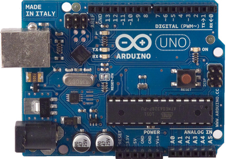
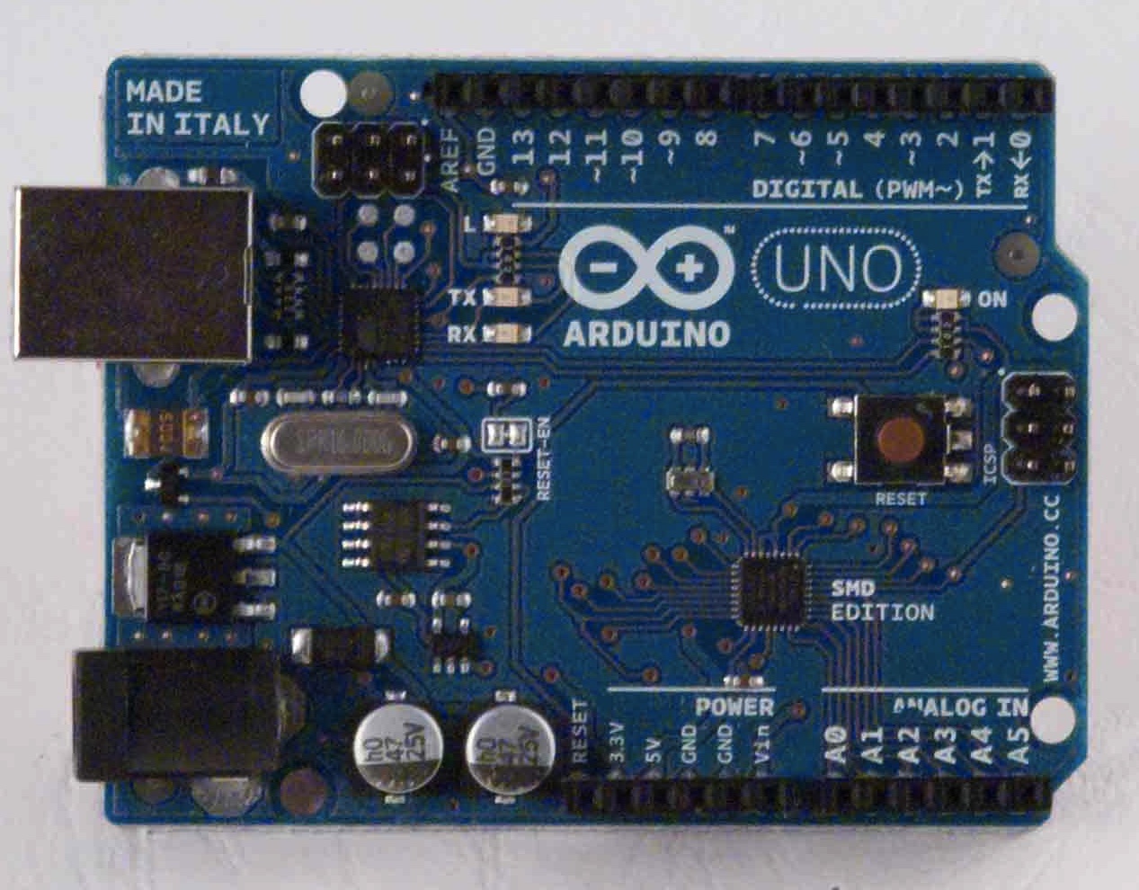
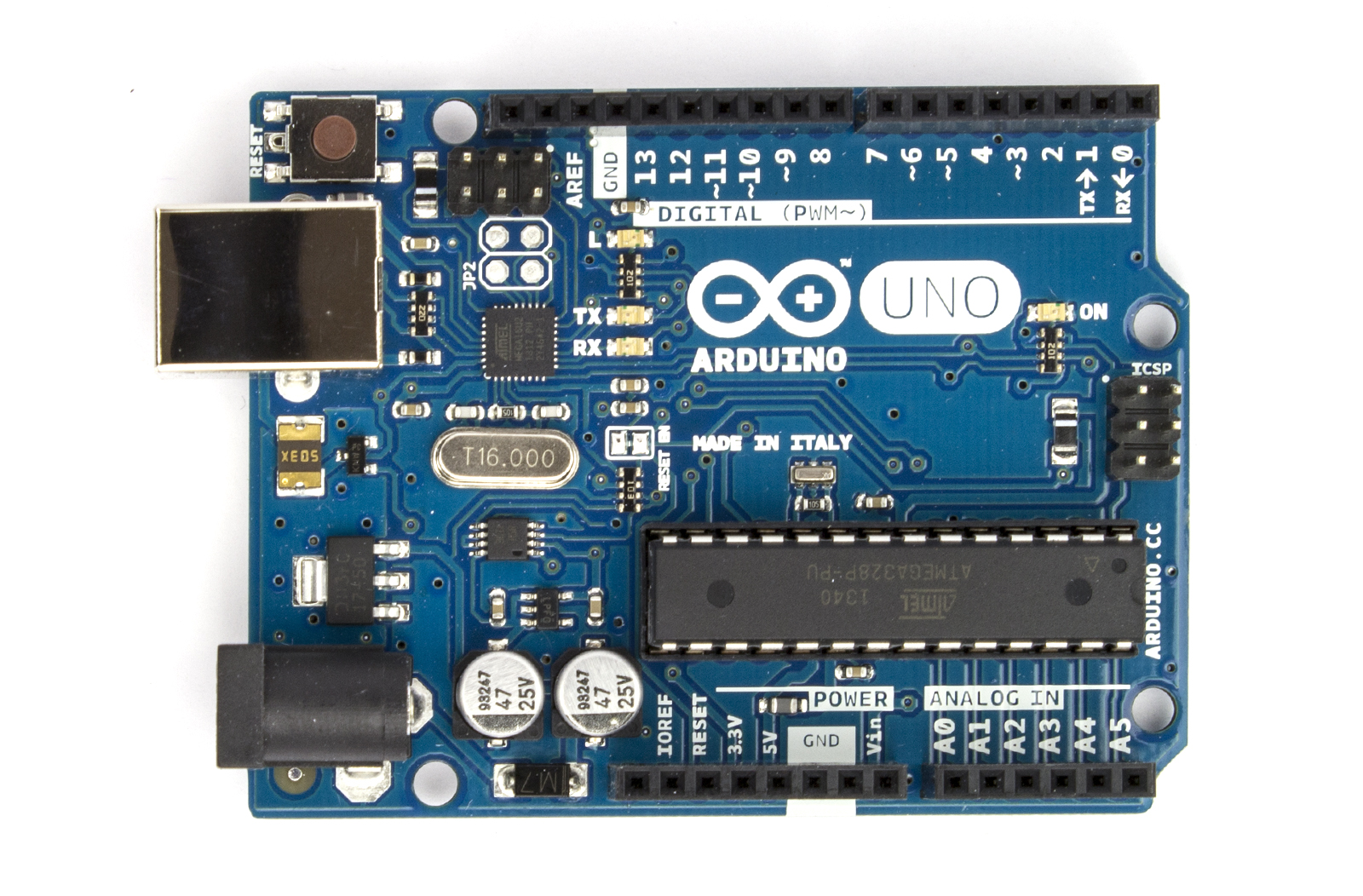
The Uno should be a fairly familiar board if your into electronics. Its one of the first boards released by the Arduino company: early versions had D-sub interfaces, migrating to USB and eventually to the current Rev 3 boards and some SMD editions. 
Early Arduino Uno - Wikipedia
Later Versions had USB
The Rev 2 (Version I own) notice the interface chip next to TxRx LED's is offset 45degrees
SMD Edition
The Rev 3. Notice the position of the reset button
There are also loads of Rip-off versions, nothing wrong with them, they may be cheaper, but I prefer going with the real deal.

I have the Rev 2, based around the Atmel ATMEGA328P: 28-pin DIP, 8-bit micro controller. Beauty of this version is if the chip blows, you can buy a new one either programmed or un-programmed and swap it out. If its un-programmed, you will need to program a bootloader to it through the ISCP header: Olimex Programmer Review

However, on mine, A0 is busted. So in the meantime until I get another chip ordered, I thought I'd figure out a way of how to get more out of the other analog inputs.

A simple way of doing this is to use an analogue switch IC. You can use a multiplexer, but analogue switches can usually work both ways, whereas multiplexer & demultiplexers can only usually work in one way. Also make sure you have an analogue switch or mux/demux for analogue applications and, digital ones won't work as required!

As mention above, analogue switches work both ways, so you can have one input accepting a number of sensors, for example, or have 4 inputs from 1 sensor. Also they can be good for auto-ranging circuits or gain adjustments circuits, by clicking in more or less feedback resistance.

The Setup & Code

I'm basing this around a DG409. Its an array of analog switches in various configurations. The 409 is 2 sets of Single Pole, Quad Throw (SP4T) switches. Each position is selected by the address pins A0 & A1. Its all there in the datasheet.

With this I was able to connect up a number of sensors to one bank of switches:
  • S1A: pull-down switch
  • S2A: A voltage divider (div. 10) from a higher voltage supply
  • S3A: An LDR
  • S4A: a Pot
I then connected the pin DA to the analog input and some digital pins to the address pins A0 & A1 of the DG409. The full setup is shown here:


I'm using an interrupt switch on pin-2 so I can cycle through the different sensors at any time.

The COM or output of the DG409 (white wire) is connected to the A1 analogue input of the UNO. This now essentially has 4 inputs now on one analogue input! All i have to do is program a way to change the address each time I press the interrupt switch.

I managed to punch out some code in under 15 mins:


So a breakdown of the code:

  • In the setup I have declared some pins as outputs, set pin 2 as the pin to activate the ISR (Interrupt service routine - https://www.arduino.cc/en/Reference/attachInterrupt), and started the serial monitor going.
  • I then declare the integer sens to be used to select the address of which switch to select on the DG409
  • The loop basically reads the analogue input A1 and prints it on the serial monitor whilst also printing which sensor its looking at. it does this every 500ms using delay(500);
  • The ISR is where most of the work is:
    • 1st it checks if the integer sens is less than 3, if it is then it can be incremented
      • if it is not less than 3, it resets it back to 0 again.
    • it then checks the value of sens using a switch-case and sets the outputs 8 & 9 to the appropriate logic, and therefore address for the DG409 - truth table of addressing can be seen in datasheet.
So in my example, sens: 0 = pulldown switch (addr: 00), 1 = divide by 10 circuit connected to a 30V variable supply (addr: 01), 2 = LDR (addr: 10), 3 = pot (addr: 11).

Results

Uploaded the sketch and opened the serial terminal:
Pressed the pull down switch for about 5 seconds

Adjusted the 30V supply from 30V down to 0V
 So in this case at 30V my full scale was 574.;
574/1023 x 5V = 2.8V;
2.8 x 10 = 28V, well I did have the fine adjustment turned down (its an old supply) so I'll take that as correct!
The LDR output. Here I was moving my hand over the LDR

POT adjustment, rotating to both ends.
It all works as expected. So that's a win in my books.

Conclusions

Well it works, its pretty simple to do and you can get a lot more I/O for very little extra cost and effort.

However there are limitations:
  • Time frame & speed limits - if the sensors require fast monitoring, and you have 4 of them, then you have to switch between them all really quickly.
    •  This takes time and to get an accurate reading at a given time frame (say 1uSec) and the time it takes to go through them all takes 10uSec, then your going to loose some data on that sensor whilst reading the other sensors - so bear this in mind. 
    • Make sure your sensors a slow when compared to the speed of the UNO (or whatever board your using) or utilise some sort of averaging in your programming.
  • Giving up some digital IO - ok its only 2 pins! But if your applications uses lots of digital signals, then you might have to work out some sort of addressing or serial interface to your analogue switch, or find a switch with some serial interface.
Those are the only 2 major ones I can think of.

Changes?

So why did I use the ISR: well because between each reading I was waiting 500ms, which is quite a long time, so I needed to interrupt right in the middle of a delay function, rather than wait 500ms to check a change in state of the sensor select button.

I could have just collected the data from all the sensors and spat them at the serial terminal in one go, that too would have been quicker.

I did originally use some port manipulation to set the address of the switch. but that meant a lot of pins weren't being used and would look somewhat intimidating to noobs. Have to be efficient yet friendly. Though if any noobs are reading this then: seriously, click on the link and go tinker, its a function worth knowing.

Anyway, this should help if you are looking to get more I/O out of your UNO, or any dev. platform. Go have fun!

Thursday, 2 July 2015

Constant Current Source - Back to the drawing Board

So, I'm right in the middle of moving. New digs, bigger house for the family and, as a bonus, a Garage with an apex roof! More storage, more room to tinker, its gonna be biblical!

Ask a question...

...get a different answer! Its a typical case of asking a question and then someone points out something else, opens a massive can of worms.

http://www.eevblog.com/forum/projects/i-should-know-this-but/

So this lead to some interesting research. Parallelling MOSFET's is not as straight forward as it seems...

The Issue

So compared to my original sec of the constant current driver, I was off target to reach a max current of 7A. It was turning out to be 5A. And although Parallelling MOSFET's was the right way of going about it, I was doing it wrong: http://www.ixys.com/Documents/Articles/Article_Linear_Power_MOSFETs.pdf

Because each FET does not have exactly the same RDS or VGTH. This effects the Drain current, ID. This means that each FET will not pull exactly its equal share of current. This can cause a number of problems: One is one FET gets hotter and this changes the value of RDS. But there are also 2 modes where the RDS has positive and negative coefficients in the Linear region and the "fully on" region. For a constant current source, these MOSFETs will be working in the linear region, this means the the RDS has a negative tempco and as temp goes up, RDS goes down, more current flows, FET gets hotter and before you know it your MOSFET is smoke!

Take the proposed circuit above and the Total current It is 5A, therefore the voltage across the single shunt/source resistor R1would be 5V for a 1OHM shunt. The same MOSFETs aren't always cut from the same die, as it were: Q1 could have an RDS of 0.1OHMS at a VGS of 3V and Q2 could have an RDS of 0.105OHMS at the same VGS. The data sheet does have these curves of RDS Vs VGS 

This means I1 does not equal I2, I1 could be 0.5A and I2 could be 4.5A, yet you'd still get the same voltage drop across the shunt resistor, R1, the current is therefore unbalanced, Q2 bears most of the load and eventually, regardless of heatsinking, it goes pop!

Even if the datasheet say its bang on, if one FET is 1oC warmer or cooler than the other, it could mean the difference between a few milliOHM's RDS

Have a look at page 3. for the FDP6670AL -  it shows all the graphs.

Amongst other things Wong with the design: the LM324 was pointed out to be, well; a bit shit! Really bad offset voltage.

So how did I overcome these problems...?

Some Changes

First off; a better Op-amp: LT1014 - low voltage offset, same package and pinout as the LM324, and I have some in stock, perfect.

So that was easy, but now had to put thinking cap on about my FET array.

Instead of using 1 series shunt resistor and one Op-amp to do the control, I decided that 4 MOSFETS, each with a series shunt resistor and control op-amp.

As mentioned before though, someone will pick your design apart, and usually not in the area you asked your original question, you know: "you do know that...?" or "I'm surprised that works!"

Well that's exactly what happened, not that I'm ungrateful for it, far from it, ignoring criticism is a fatal mistake I find, that's if its constructive!

Seems my feedback network was somewhat thrown together (see Current Source Update for schematic): C8 & R18 on the output of U1:A are there to suppress some ringing on that output which showed itself on the load source, not desirable. So I just threw in a LP-RC filter and it got rid of it.

However I didn't measure the transient response, didn't even cross my mind to be honest. I referred back to the design I was taking my inspiration from and he had saw he had an RC in parallel in his feedback (R7 & C5). Possibly to compensate for the slow reaction time of the system to stabilise.

Someone else on the forum suggested that I reduce the output impedance of U1:A by using an emitter follower and that this would improve transient response too.

Only one thing for it: TO THE SIMULATOR!

Testing

3 circuits to test

  1. Standard feedback constant current driver - no compensation nor common emitter output
  2. Compensated feedback - as above but with an RC in the feedback network
  3. CE output stage - standard feedback with a CE output stage
The shunt resistance will be the same in each design: 1OHM.

Each circuit will be test 10uS rise time stepped input first for 2.5A load current and then 0.1A. So VREF in each will be set to a max of 100mV and then 2.5V. So lets have a look at the results

Circuit 1: standard circuit


RED = Gate voltage signal
GOLD = Load Current
BLUE = inverting input / feedback
GREEN = input signal/ref

As it can be seen there is some minor overshoot on the gate voltage and this also shows on the load current. So it'll overshoot by about 100mA and takes about 15uS to settle. Now lets look at 100mA:

Dear god! Well that's serious overshoot if ever I saw it! Clears the set point by 60mA (160%)! not good!

Lets see if circuit 2 is any better?

Circuit 2: compensated feedback


RED = Gate voltage signal
GOLD = Load Current
BLUE = inverting input / feedback
GREEN = input signal/ref

Really not that much difference at 2.5A, least not that I can notice.
100mA?
 Same as circuit 1 again. it doesn't seem to do much for the transient response anyway - might be doing something wrong here

Circuit 3: CE output of op-amp

 S when compared to the other 2 you can see the Gate voltage lags a bit behind the reference signal, however the overshoot seems to be lower and the settling time seems faster.

I didn't do a 100mA transient response cos I did some playing about and reduced the value of  R4 down to about 100R and repeated the above response.

The overshoot is much lower than R4=10k and settles much quicker. The gate signal still lags by a couple of uS but its not worth complaining! Here's the best bit at 100mA transient:
Wow! Compared to the other 2 that is pretty good! Very little overshoot and fast settling! I think we have a winner!

Conclusions

So why does this work - well I haven't done much research, but it looks like larger current gain by employing Q3, essentially making Q1 & Q3 a hybrid BJT-FET Darlington pair.

If I remember my control systems correctly, larger gain = faster response/sensitivity (https://en.wikipedia.org/wiki/Control_system#Proportional_control - paragraph 2) - which rings true with the vastly improved overshoot we see.

Edit: I have recently been corrected above: the output impedance from the CE stage coupled with the gate capacitance, forms a 1st order low pass filter that has better phase response than that of just the op-amp output connected to the gate - lower resistance - lower phase shift - better loop response. I'd like to simulate this effect and post it up later.

So I guess then I'll be doing a new schematic for this project then. But on top of this improvement, some more additions:
  1. use 4 of these circuits in parallel to sink more current. Each shunt resistor will be a 1OHM 7W ceramic resistor. This means I can sink 2.5A per channel, meaning a total current of 10A! Mega!
  2. Cos each channel is now 2.5A I can change my reference voltage to 2.5V, and guess what, I have some AD680 voltage references in DIP-8. Really good tempco on them!
So I now have a more precise, and better performing design, that exceeds spec! the max power I worked out to be about 68W, which is still ok, but not an improvement over the first design!

So I have a max rating for my design: 30V, 10A, 68W - so long as any of these are not exceeded, it should work.

The Down side: the only thing I can see is I have to employ another op-amp to do the current control, but meh, its not too difficult!

Friday, 26 June 2015

Grumblings: Part 2

So I managed to refit the gearbox back on the engine after a length strip down, removal of the differential bearings and re-fit of the diff bearings.
So how did I get to this point? Surely stripping down a gearbox is a perplexing and herculean task?

Its not as bad as you think. Most of the job involve some lateral thinking, careful disassembly, a clean work surface (an old towel mopped up leftover oil) and careful recording and keeping all removed parts laid out in comprehensive way.....(yeh right!)

Homework

Firstly its good to get an idea of how a gearbox works:
This video should explain how a gearbox changes gear. Thanks to +Land Rover Toolbox Videos for putting this video up.

The next video explains briefly how front wheel drive transmission works and +Engineering Explained does draw a pretty accurate depiction.
 So armed with this, its time to move onto disassembly. Obviously, its not as simple as undoing a few bolts, its a complicated mixture of specifically torqued bolts and nuts. I approached with caution and left the BFI on the shelf. One wrong swing with a twatting iron and its game over!

Disassemble

To start: I remover the aluminium cover off the back of the gearbox.
Here there were 2 gears held onto the shafts with 2 staked nuts. The left shaft is the input shaft, the right is the output shaft that drives the diff. I removed the staked nuts by wedging an old towel between the gears and then using a 32mm socket, running the bolts off with an impact wrench. This stripped the indent in the nut and came off pretty easily without stripping the threads.

Then removing the gears I kept the dog-teeth gears and together with them placed them in the ali casing - this was to remind me that this was the parts that go under it.

After that I removed the bolts that held the bell housing to the gearbox housing - 17x 10mm head hex bolts. I then tried to lift the housing off but couldn't. After trying to find a locking clip inside the box between the gap of the bell housing and gear housing, I realised that the 2 bearings under the 2 gears I removed earlier had captive clips held in place with 2 torx head bolts each....and we're torqued up to the hilt!! A cheater bar on a 1/2 drive trox bit loosened it off!

Once the 2 clips came off the gear housing slipped off revealing the glorious tower of cogs!
The forks that push the dog teeth gears to select gear are held onto the selector rod with roll pins. Some of these had to be tapped out enough to release the rods so the gears could come out but with tapping it all the way out to keep parts together.

After some  jiggling it all came out, the reverse gear lifting arm came out by just pulling a pin and lifting it out. The gear itself is on a loose shaft that just lifted out.

With the gears removed, the plate needed to come off to free the differential. 2x 10mm head bolts and 9x T50 torx socket bolts. These are on really tightly! So using a 1/2" drive ratchet or cheater bar is highly advised. One of the torx socket bolts is blue and holds the selector rod that pushes the selector forks up and down.

The races were tapped out of the bell housing and gear housing. These were not in that tight and came out with a few swift strikes of a hammer on a drift. This had to be done to get the part number off the races. Here is a video of a brief look at the insides:
Once the diff was free, out came the Dremel death wheel and carefully cut a slot in the cage holding the rollers in the bearing and then removing that and then another slot in the inner race and then bashed it with a wide angled old screw driver to break and release the inner race and remove it.


Diff was now ready to receive the new bearings.

The bearings went back on with using a press or even dropping the diff in liquid Nitrogen, which was offered by works physics dept! A couple of deft taps with a hammer on the correct size socket and they were refitted! Fitting the races were equally easy, using the old races as a drift.

Assembly

Put the diff back in and put the plate back on. By chance I found a little metal nub with a spring in it. This was the reverse locking pin! It must have fallen out when I bashed the races out, so be aware of this! I popped this back in the recess underneath the reverse gear selector pivots.

Torque down all the bolts as hard as you dare, the housing is only aluminium, too hard and you risk stripping the threads, too loose and the plates not seated enough. For the Blue headed bolt, a little less torque than the others - I have no torque specs unfortunately, but they were on really tight when I took it apart, blue one less so.

Getting the Gear towers back in was a ballache. The selector rod from the linkage had to be disassembled and then all the gears all re-fitted and then the selector mechanism re-assembled.

Then you realise that you left off the reverse gear....right after you have re-tapped all the roll pins!

It takes some time, so be patient and test as you go: move the selector lever to verify (push it in and out and left and right in all combinations): if it looks, sounds and operates right (take note of the selector lever position below this is the general orientation it should be fitted).

Once all the gears where in and looked in the right place and moved the selector about to go through the gears I put a bead of silicone around the whole outside of the mating surface:

I slid the gearbox housing over the top and tried to squarely plonk it down onto the mating surface. some silicone did squeeze out, but that's normal. Again take the bolts that were holding the bell housing to the gearbox housing and torque them up on opposite sides rather than going round so that they are mated evenly.

Replace the 5th gear assembly and selector fork, replace the C-Clips and tighten the torx bolts to hold the gear shafts in place. Tap in the roll pin to hold the selector fork for 5th gear in place. Fiddle around with the selector lever to double check that it all works good.

Next: I stuck a towel between the teeth of the gears and spin the staked nuts back on. I tighten them till the section that was dented is back in roughly the same position where the flat spot on the threads are, don't just position them, they have to be tight! I took a blunt chisel and smacked the nut so that it deformed back into the flat spot. A final test spinning the drive shaft with the impact driver at slow and changing gear confirmed that it was working correctly including reverse gear!

PHEW!

I wouldn't take this way of doing it as gospel, admittedly I did cut some corners: I should have got new staked nuts, but they did the trick:

Refitting the engine

Long slog to driveway!
With the engine back in the barrow, it was back down the garden and to an awaiting engine bay! Getting the engine back in was actually quite easy, the only hard part was trying to get it to line up with the mountings, but once you have it, its not too bad. 

Cos I'd marked up all wires, that too was an easy task. I had it fitted and hooked back up within an afternoon!

Before I refitted the airbox and battery, I refitted the drive shafts and filled it back up with oil through the breather (its a funnel like plastic thing on top of the gearbox, which you can take the cap off): it takes 2 litres of MTF-94, don't go to halfords for it, they'll just look at you blankly! get to a place like Andrew Pages or similar mechanics supplier. It takes a with to fill it up through the breather, but cos its a funnel and of its position, its convenient!

Also reconnect the linkages for the gears, if you remembered how they went on. it should be apparent as they will struggle to fit if the wrong way. Check before you put the battery box back on: 1st, 2nd/3rd,4th move the selector front and back, selecting between 2nd & 3rd & 5th should move the selector up and down.

Battery box back in, air box back on, ECU hooked back up and battery hooked up, I refitted the radiator and some of the lights and horns: time for a start up!

So did I fix it?

Well there is good news and bad news:

The Good:

  1. Engine started first turn! mint!
  2. Clutch worked, 1st, 5th & reverse took some effort to go in, but it changes gear like a treat now, much smoother!
  3. After realising I had seated the linkage cables in the forks incorrectly (the metal clips on the boots should sit in the forks) that problem went.

The Bad:

  1. The problem is still there! BOLLOCKS! but its no worse than before this job!
  2. I had to hack the exhaust back on cos I took a grinder to one of the bolts that were rusted up. The bolts on the tail pipe are captive, so I had to grind the surface where the cut bolt had been flat and drill a hole and use a nut and bolt with a spring washer. I'm not getting gassed, but it's blowing really bad!
  3. replacing the belt tensioner did nothing - it still squeals! So I suspect and incorrect belt fitted!
So I'm essentially back to square one! The only other thing is the the input bearing in the gearbox! If it is then I may as well just buy a kit and do the whole lot, but at £120, its money I don't have, but would be lot more if I got a garage to do it.

But hey! Least I know what to do now!

Monday, 8 June 2015

Grumblings

I guess you could call this my first video blog. Here are some ramblings about taking an engine out of my mini cooper.
So after I managed to get an engine hoist, kindly lent by my neighbour, I pulled the last nuts a bolts holding the engine in and single handed coaxed the engine out:
Good day to pull an engine!Glorious!

Flying engine!
Given the alley down the side of my house is too narrow to get the hoist down I had to find the wheel barrow and use that to get the engine near the shed. Well i wasn't just going to leave it on the drive way!

Mental power to weight on this baby! lol!
serious weight loss!
The damn thing is heavy! About 150kg. Wheeling it out to the garden in a barrow took about 15mins by myself. Once in the garden I wheeled the hoist into the garden and lifted it out of the barrow and onto the hoists beams with some wooden joists.

Once in position, it was a case of relocating the tools to the garden and begin removing the offending bolt from the starter to remove the gearbox from the engine. and low and behold, the friggin' thing had been cross threaded!! I was bloody lucky I didn't shear it!
 I later managed to reform the damaged thread and tap out the hole in the bell housing, now it screws back in with ease.
night shift!
So with gearbox off, I could get access to the clutch, which a new one was fitted, 15 min job, and the gearbox was taken into the shed for further operation! A tarp round the hoist to keep the elements out of the engine. Good time to stop for a beer and chill out!!

Wednesday, 3 June 2015

Olimex are watching!

Cast your mind back to April of 2013....(cue wavy visuals!)

Yes I posted my brief review of the Olimex AVR programmer and programming a Bootlaoder to an arduino uno.

Well turns out I need to upload refer back to it as the ATMEGA328P-PU on my board has had a falling over and A0 is shafted - it either reads the upper 1/3 of the supply or low. So I'm going to buy a new one and burn a bootloader onto it using the Programmer.

Read through me old blog - Clicked on the link for the manual for the programmer, had a scroll down and saw this....
Look Familiar?!
YEP - the buggers at Olimex read my blog and took my bloody schema! Not that I'm pissed off, more that they could have said thank you!

Not to worry +OLIMEX  (didn't know you were on google+), glad I could help!