Sunday, 16 February 2014

Just how conductive is conductive ABS?

So a good friend of mine does a fuck-ton of 3D printering (Shameless advertising here!)

I was round his workshop today to help fix a bit of car trouble. Alas; turns out OBD and OBD2 are not the same creature.....nevermind.

What he did show me was some "conductive" ABS he had and wanted to do a project with it. I was sceptical - I had come across conductive plastic before and you either had to pump a couple of 1000V into it before it would conduct or it was only good enough for ESD/EMC purposes.

Basically "conductive" when used in terms of plastic means VERY high resistivity! To an electric source: its a resistor of MAHOOSIVE resistance!

A few Youtube hits yielded some interesting results - but one piece of information cropped up, if conductive ABS bends/deforms: it changes resistance.

This means it could have applications for:

  • home made strain gauges
  • bendable potentiometers
  • movement sensors
  • weighing heavy masses - e.g. a car
So, trying REALLY  hard to remember our GCSE physics we did some thinking. (seriously there was smoke coming from the top of our heads!)

What we wanted to do was find out what the resistivity (ohm/metre) of this ABS was. Seen as all the bag had on it was "Conductive ABS" on it, this wasn't much help! Nor could he remember the supplier to bring up some datasheets.

The Experiment

Initially we thought: Right just bang an DMM in resistance mode across it!

Tried it and got diddly squwat! meter didn't budge.

So I came up with a better idea! Apologies for the lack of photos folks:
Jez had a bank of batteries on his desk he'd pulled out of something. I had a automotive DMM (in my tool box) with a micro-amp range on it. I was sceptical as to how precise and accurate it was, considering it cos about £30 - but give it a go.

Some Croc clips and about 4" of this conductive ABS and the circuit was constructed. Battery voltage was confirmed to be about 5.2V from a quick test with the DMM - DMM means Digital Multi-Meter by the way.

I first took a current reading at 40mm from positive point to negative point. Reading on ammeter said about 10uA. Same process again but at 50mm - current = 7uA. OK; this was enough data to just get a figure that should give us a sensible answer.

The Maths

OK so from experience - I found conductive plastic was in the hundreds of ohm-metre range.If I got 2 readings in the 100's of kilo-ohm-mm range then I knew we were in the right ballpark!

OK so from trusty Wikipedia - Resistivity:

  • roh( the p shaped symbol, which I'll use p for) = resistivity in OHMS-metre's
  • R = resistance = Voltage / Current
  • A  = cross sectional area of ABS
  • l = length of section that current is flowing through
Diameter of ABS filament = 3mm, therefore radius was 1.5mm. this gave a area of: 7.086mm^2

So for 40mm:

R = 5.2 / 10uA = 520,000 OHMS

Substituting R into the resistivity equation:

p = 520,000 (7.086 / 40) = 91891.585 OHMS-mm

(Remember: always keep units the same, don't mix cm with mm for example.)

OK: so roughly 91K - not bad, 10K shy off target!

Solving for data obtained at 50mm:


R = 5.2 / 7uA = 742,857 OHMS
Substituting R:


p = 742,857 (7.086 / 50) = 105,277 OHMs-mm

OK: so about 5K out from target, looking good.

So you could sat that the resistivity of this sample of ABS is ~100kOHMS-mm or ~100OHMS-metre (as there are 1000mm in one metre)

Outcome and findings

So considering plastic is usually a good insulator, you'd think 100 OHMS-m is still resistive, and that conductive ABS is just a con - when actually this IS conductive for plastic!

Plastics can be in the order of 10's of Gigaohms-m (depending on plastics).

Also: this experiment cannot be trusted - turns out there are 2 measurements of measuring resistivity: Surface resistivity and Volume resistivity.

With the configuration of our experiment, we may have been measuring surface resistivity; so the current may have been flowing around the sample like a tube not through it.

As a result - the resistivity could actually be lower? Saying that: this was on fresh ABS: its properties could change after being extruded into a 3D object.

Another note: I wouldn't consider relying on conductive plastic to make your own resistors with a 3D printer - the tolerance on them will be shockingly bad - so I wouldn't expect 0.1% on values!

So: I'll leave you to pick holes in my Back-woods experiment - but it does demonstrate how you can use some bits lying on your desk to quickly determine some material properties!

Also that my micro-amps range on my £30 DMM probably works to a decent degree of accuracy!

Monday, 27 January 2014

LCD's on Ebay

LCD, Matrix Orbital LK204-25, 20x4, white Text on Blue, RS232, TTL, I2C

Roll up, Roll up, Roll up! Screens are on EBAY!

Get em while they're hot! 
Managed to verify that 22 are working, turn out I had less than 30 at last count, considering I gave a few away!

I am doing international delivery, if your country's not on the list, then drop us a mail, and I'll see what I can do for you!

Thanks for viewing!

Friday, 24 January 2014

"Trash" find screens - testing

About a few months ago, I caught one of my work colleagues throwing out some parts from a project long since mothballed.

"They're all going!" - nod from my colleague; I told him to put them to one side, had a chat to higher ups to make sure I could "acquire" them: "If you can pull em, you can have em! Bin wagons due in 3 days" - managed to pull out roughly 30 screens out of these dud units along with more stepper motors than I knew what to do with and about 30 V-Drives (that's for later).

About half the stepper motors went to a mate who was building a 3D printer - I think he's set for about 8 printers!! But as a thank you, he bought me a Erbauer grinder + blades (SWEET!), which I needed to do some work on the landy - which reminds me, I should post some work I've done on that thing on here!

So did any of these screens work? Some were still in packaging, some I'd removed from fittings but didn't even know if they actually would power on, so I did some digging:

The Screen

Its a 20 Character by 4 line LCD which is backlit in blue and with white text. That's all I knew about it when I first looked at one. After a google: JACKPOT - Matrix Orbital - VK204-25

Turns out it had more connectivity than any other LCD I'd seen: I2C, RS232, TTL, USB, RS422 & Dallas 1-wire (new to me anyway!). I was doubtful about its USB capabilities as I could not see a USB port on it, but it had footprints for one.

It also has an input for a keypad and a set of 6 general purpose outputs.

Physically, it is a 2 boarded device; by that i mean it has one board that appears to handle the communications protocols the user selects and the board with the screen fitted, which I assume is a standard LCD based around a Hitachi HD44780 LCD controller. I assumed this from the interconnecting header between the 2 boards: its pretty similar to most LCD's out there and seems to be a standard that many manufacturers seem to adopt - but from the data sheets and info I can't verify that.

I suppose by that observation, and if you were deft enough, you could pull the LCD Board away from the interface board, if you just wanted the LCD on its own.

Getting Started

When I had pulled them out of their units they were connected by a 4-way molex KK header, which turned out to be the TTL & I2C port, with power pins. I had heard of I2C and have designed systems for I2C devices, but never actually got to grips with it - this opened a perfect opportunity to pull out the Arduino and get started.

Fortunately; Matrix Orbital supply an some demo code designed for  the Arduino environment:
  • Arduino I2C demo - it's technically not for this screen, though if you pick it apart, it works
  • LVK204-25 serial demo - opens download from googlecode in .ino format, no documentation unfortunately but will allow you to communicate to the device if its set in RS232 mode
I whittled up some pull-ups onto a bread board and linked the connections for the I2C bus via them to the Arduino:
such a tidy desk....its not like that now!


I then pulled the Demo sketch apart and managed to get it display text, as above. Now that I could get it working, I decided to expand the setup so I could test them all.

Test Development

To ensure all aspects of hardware were functional, I decided on a set of tests:
  • Make sure the backlight works
  • make sure that there aren't any dead pixels
  • test to make sure that the contrast is good
  • make sure that it can display test legibly -  and not garbage/corrupted
  • test that the General Purpose Outputs are working
This I thought was enough to go on to ensure that they weren't buggered. I thought about testing the keypad input, but I thought that its mostly a device based on outputs and not to bother.

I decided that each test would loop and then press a button to confirm that test had passed and then move onto the next test. The test takes a little longer then if it went though each test automatically, but I wanted to do something with interrupts to prove to myself I could do it.

After some tinkering with the contrast functions, I decided that I could perform a dead pixel test by ramping the contrast up to full and look for empty spaces in each segment.

So I came up with this setup:
Here's a picture of the back of the LCD to show where all the connections went:
Connections to LCD - 4-pin KK is comms & power, 6-way header is GPO. D-sub 9way can be seen for RS232/RS422
The LED's are 5V rated, hence why there is no current limiting resistor on them. I added a resistor & cap to the switch as while testing the code, there was alot of debounce on the interrupt, causing it to skip tests.

After a few trials I settled on this code:


I'm not sure if i should have included the Wire.h library (is it included by default in the arduino IDE?). Anayway; you power it up, after the screen has been setup by running the function LCDSetup(), the while loop runs the the SwitchCase to check the test number it should do. Each time the interrupt button is pressed; the integer: Test is increased by 1, so long as it doesn't already =4, as there are 4 test and going beyond that may cause it to take a hissy-fit!

With each case, is a function to perform a test; within them are the relivant functions to send values to the screen for Backlight brightness, contrast & so forth by using Wire.beginTransmission to the I2C address specified in the beginning of the code (#define I2C_address 0x28, as specified in the manual)

And here's how it worked:
Backlight test

Contrast/dead pixel test

Alpha-numeric test

The Welcome screen

Toggling GPO

The setup


Issues

One minor issue was that the interrupt didn't take affect instantly, it only kicked in till the test had ended. Its not that bad.

One other thing I found: whilst testing some screens that were already packaged; the would power on but only displayed the default screen. After a quick read of the manual: i found that you have to solder some jumpers onto the board to enable the mode you require:
Notice the solder bridges made in the area marked I2C - this means its in I2C mode

Here: there are 3 0R links in the area marked RS232, just under the silkscreen text LVK204-25 - this means its in RS232 mode.
Also you will notice there are some track going from the jumper pads for the RS422 mode, leading to and un-populated IC footprint: U8. This also means that RS422 is not likely to be featured on this model of screen.

I'd like to point out at this point that this is why you RTFM!
I found that un-soldering the links from RS232 and bridging over the pads in the I2C area, I managed to get the screen to work on the test bed. So by default, they are shipped in RS232 Mode.

Outcome

I'm now using this test bed to verify the screens I have work. This is cos I am selling them! yup, they're going to be up on ebay! once I've tested them all, I'll be posting a link up on this blog if your interested in buying one.

They make a great tutorial tool and an excellent display for any project. Plus can expand the outputs of a micro controller project if needed (say you were making a project with an 8-pin ATiny?)

I suppose I learnt a bit more about functions, switch/case, more about using interrupts and a I know more about communicating with device than I did before. At least from this end of the device!

I must admit my code is very messy and thrown about, I really need to hone my skills getting the functions onto one sketch and reference it in the main sketch - something I could do next.

I will be saving a few screens for myself. I would definitely get one - they are quiet a useful little thing, even as a beginner you can learn a lot about I2C.

Feel free to pull my code apart & watch this space for the ebay link if your interested

Tuesday, 1 October 2013

Trails & Tribulations

So as promised, here's the ins and outs of trailing.

How I got into Trailing

I first got into trailing after I got in touch with an old mate of mine. I was a bit down after a break up and was watching Love The Beast. I am a a bit of a gear head anyway, so this got me inspired to get into motor sport so how....then remember: my friend mentioned he had got together with his dad to build an off-road trails vehicle.
So I rang him up and asked if I could help: 
"What you good at?" he said
"Wiring and electrical things" I replied
"Right, we could do with a sparky, see you Saturday!"
I showed up and was introduced to bare skeleton on wheels in a garage. There was quite a bit of work to do and it wasn't going to take a weekend.
So after my first weekend; hair full of oil, hands smelling of swafega, grit in my eyes and head full of new found knowledge, I decided to come back again the next weekend, and the weekend after, and the next weekend. After about a month or so's work she was ready!
Nice, new & shiny!
The first time it trailed, I didn't drive or navigate, I just watched. the second time I got offered to drive, and why not: I had a full UK drivers license and £10 for club membership & £20 for entry in my pocket. So I strapped myself in and my friend navigated. Here is one section of the event that day:
Yes...that is a pile of horse shit we are driving into at the end!

Since then I drove "Cannon Fodder" (that's what she was dubbed) for a few more trails, till I decided to go it my on and stop sponging rides off me mate.

How Trailing works

I joined the Pennine Land rover Club: who call themselves a slightly nuts bunch of land rover & 4x4 enthusiasts. I joined cos my mate was a member along with his dad and a few others I was introduced to through his dad.

Some clubs have different rules and regs but the principal is the same. 

So what happens?

I think the best way I can describe it is a bit like golf, but with 4x4's. Each event is split into 12 sections and each section has 12 gates. Lowest score wins.

A Gate is essentially 2 canes set apart with the a gate number ticket on on of the canes: this is ticketed cane must be on the drivers side of the vehicle. Between each gate are obstacles to challenge your driving skills or test your vehicles abilities. Sometimes the gates themselves are strategically placed to test the driver.
Barry attempts gate 5

Each section is set out by the clerk of the course: basically a member assigned to setting out the sections for that event. They usually turn up the day before to set out the section.

Each entered driver must then drive the section starting at gate 12 and ending at gate 1. Each gate you drive through; your score for that section decreases: so if you go through all 12, you get 0 (clear), if you get stuck between say 4 & 3 gates, you get 3 and if you hit a cane on a gate, you get the score of the gate you hit! 

Best score you can get for the whole event is 0 (12 x 0) and worst is 144 (12 x 12). My personal best is 12 for a whole event.

Then your scores are totalled up at the end of the day and the person with the lowest score gets bragging rights and club championship points and/or a prize (usually a t-shirt with clubs logo). 2nd and 3rd get club points accordingly

The clerk of the course however gets 10 points for his troubles for the whole event!

That it?!

Well not really, there's more to it. 

You don't have to but highly recommended that you walk the section before driving it. A navigator is optional, but providing they are 16 or over and not pregnant, its good to drag them along to walk the section too, making mental notes of obstacles and driving lines.
Jedi Clive advises Padawan Jezzmund on driving lines
I should make it clear at this point that speed is NOT the key when doing this kind of trailing! Your navigator does not have to by Nicky Grist and rattle off pace notes! All they have to do is remind you of lines and obstacles.


For more information, read the How To Play section on the Pennine Club Website

So Who makes the calls?

Each group or section as a number of Marshall's. These guys watch to make sure you don't hit a cane on a gate or fall foul of the obstacles.

Never argue with the Marshalls, their word is final! If you carry on arguing or misbehave you get a 12 for the rest of the sections and told to pack your shit & piss off!

So what counts as out?

  • If you hit a cane, you stop, get off section & get a score for the cane you hit
  • If you are not moving for 3 seconds, you stop, move off section, and get a score for the last gate you cleared.
    • not moving means you are stationary, even if your wheels are spinning.
  • If you get stuck in a gate: providing a wheel hub (centre of wheel) of one wheel is through the gate, that gate is cleared
    • it is worth noting that if you think you are going to hit a gate, but can get your hub through: STOP!

Vehicle Classes

Vehicles are split into 2 main groups. All vehicles are closely scrutineered before competing to ensure that nothing bad happens to spectators or the drivers + passengers.

CCV

Mark 'il championi', MB62 CCV trailer
CCV or Cross Country Vehicle are mostly towed to and event. They are divided into classes depending on profile, running gear & drive train. they don't have to be taxed or MOT'd, nor be road legal. They do however have to be fitted with a roll cage sturdy enough to hold the vehicles weight and at least a 4 point harness for driver and passenger.

Our club most commonly run this group of vehicle with rover V8's ranging from 3.5 litre to 4.2 and even 5.5 litre! though some are now entering with turbo diesels and showing up the V8 lot!

Common choice of transmissions are automatic: low range, stick it in drive, point, stamp on throttle and watch the world go backwards!

Most of them weigh in around under a ton, so power to weight is quite good!

RTV

My pride & joy
RTV or Road Trails Vehicle are road legal, have a tax disc, and MOT and are commonly driven to events. Again the group is divided into classes depending on shape and specs. Vehicle must have a valid MOT to compete as RTV class. Roll cage is not required but some form of protection from the drive being crushed by the weight of the vehicle is require, so rag top vehicles must have a roll cage.

This class usually contains a mixed bag: Land rovers old & new, both diesel & petrol, Susuki's and Jeep's.

Commonly manual gearbox. Some are heavily modified with extra Armour underneath to protect the vital parts like the steering rack, oil sump, gearbox, Transfer box & differentials: front & back! Cos if it goes on section, your driving home on the back of an AA truck!

More information on vehicle regs can be found on Pennine Land Rover website.

So why do it?

It is the cheapest for of motor sport. Forget about TopGear and their outlandish statement that motor cross is cheap, compared to trailing: you can be up and running for under £2000! It requires no special licensing for competitors. Most importantly: ITS A LAUGH!

You meet like minded folk, there is some good competition and banter, some clubs like ours have social camping events: 2 days of trailing, BBQ's and beer (though that's after the days event!). Also there are the usual Christmas and club anniversary parties (Pennine Land rover club just celebrated its 50th Birthday!!)

No off road experience is required, though its worth having a practise with an experienced driver before competing. The basics and an understanding of how the vehicle handles off-road will help a lot!

Safety gear is not necessary: you don't need a crash helmet, but if it makes you comfortable, then by all means. For RTV; a roll cage is not a requirement, but it will save your bodywork if you end up on your side.

If the worse does happen and you blow a differential, snap a half shaft of worse, then there is always a helpful soul that will lend you tools, spares or advice to get you back up and running. In my view: always help your fellow competitors. Playing by yourself is just boring!

You get to be outdoors. If the weathers good, then bonus, if not: man up and get on with it. Unless there weather of apocalyptic proportions, Trailing happens all any weather, all year round: Horizontal rain, snow, or blistering heat, its always on!

You will get mucky: the clerk of the course is 95% of the time a sadist! And will set out parts of the course though a muddy and wet part:
Here is Tony "Man-Duck" taking his navigator of the little ride! This actually wasn't part of the section :D

Checklist for a days trailing:

Spectating:

  • Water proof's
  • Stout boots
  • Lunch
  • Drink/Water
  • Change of clothes
  • Towel (wet)
  • Suncream (Sunny)
  • hat (as per weather)

Competing:

  • The above
  • sunglasses
  • Tools & a jack
  • your motor (obviously)
  • membership fee (new members / renewal)
  • event fee
  • any spares you think you may need (optional but advised)
  • tow rope (mandatory) - no kinetic ropes, steel cables, chains or snatch ropes! Must be made of none elastic or non-metal material and be able to hold your vehicles weight - see regs on Pennine Website
  • Spare fuel
  • a decent set of off-road tires WITH INNER-TUBES - if the bead on your tires breaks due to the flex in the tire off the rim, then the pressure in the tire will escape VIOLENTLY!
  • a sense of humour - there will be ribbing and banter, so leave your pet lip at home and try and keep your toys in the pram. You never know, you may get your own nick-name at the end of the day (some of the clubs favorites: Cane Killer, Dangerous Brian, Grinch, il champioini, jezzus, Gobby, Man-Duck)
So......You fancy it?!?

Thursday, 26 September 2013

Absence

So I've not blogged for a while. Mainly cos I've been Uber busy doing fatherly and land rover based things.

Some of the landrover based things could have been blogged, but its like painting the forth road friggin bridge! So understandably, I've not had time to Blog.

Rest assured I'm planning on returning, and first by posting (as promised) about the trails vehicles I've helped build and a little about trailing......

Tuesday, 2 April 2013

Olimex AVR Programmer

A bit of a Heads up!

Whilst messing around with this programmer, I found you can accidentally over-write the boot-loader on the Arduino by uploading your program through the ICSP header!

SO YOU HAVE BEEN WARNED IF YOU PLANNING ON DOING THIS! I DID NOT BREAK YOUR ARDUINO! It just needs the boot-loader re-loading! See below

Bit of Background

So with some up and coming Arduino project coming to a close, I want them to become stand alone widgets, where they can be soldered onto a strip board and utilise a controller of their own, like the ATtiny range of micro controllers.

ATtiny85 - Small, dip-8 package, really useful
You can program chips on breadboards using the Ardunino as a ICSP (In Circuit Serial Programmer: ICSP wiki definition)

I found this Link: Programming an ATtiny with arduino, a while back and managed to program an ATtiny85V with the Blink sketch in the Arduino IDE, which as proof enough that it could be done for me. Big thanks to those guys at High Low Tech, MIT!

However, this kinda makes your Arduino tied up doing tasks that something else can do. So I purchased an Olimex AVR-ISP-MKII.

Unpacking and Setup

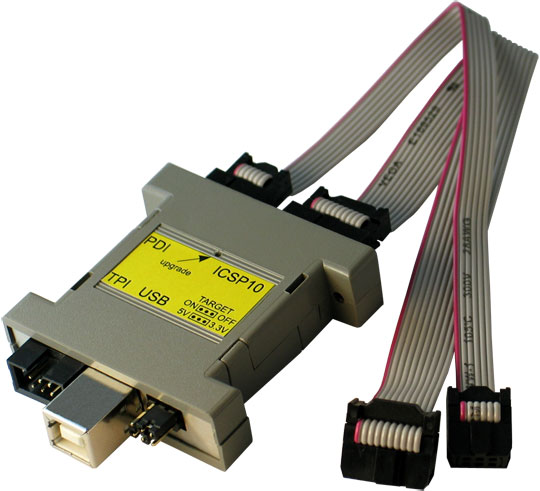
Device comes in a cardboard box with company decals on it. Inside there are 2 ribbon cables: 1x 10way & 1x 6way, and the programmer itself.

As you can see from above they have managed to squeeze the whole thing in a 25way D-sub, what I call "gender-bender" housing (usually cos I find this type of housing is used for swapping sex's of D-Sub's).

There are 4 connections on the device:
  • USB
  • TPI - Atmel's Tiny Programming Interface - for programming ATtiny's
  • PDI - Program & Debug Interface
  • ICSP10 - In Circuit Serial Programming

I'll mostly be focusing on the ICSP port here.

There is also a pin header that allows you to switch power to the target device on or off and either 5V or 3V3.

There are 2 LED's too to show the status of the programmer. 1 orange LED and one bi-colour LED.

After a quick skim read of the manual off the the suppliers website, I realised to use this programmer with AVRDude or the Arduino IDE, I had to reflash the firmware on the programmer.

Manual is: Here

Installing the drivers went well and the firmware re-flash went as per the instructions described.

Bloody Teething Troubles

As with all hardware you except to work out of the box, it didn't, nor was the Manual helpful beyond this. instead of a Green LED coming on, it was now red and the orange LED was on.

First thing was to see if i could program the arduino board through the ISP 6-pin header on the edge of the board.
ISP header shown below the reset button
 Given the ICSP header on the programmer was a 10 way, I assumed it was the other 2 headers, which were 6-way, meant I should use either of them.

With the 6-way cable in the TPI programming port and the other end connected to the Arduino (target), I loaded the Arduino IDE, and made sure that the right programmer was selected:

I then opened the blink sketch and uploaded the sketch like so:

However it didn't work and got the following error:

First thought was that the upgrade went tits up! The manual told me everything about when it should work, but not when it doesn't & the trouble shooting section was quite short!

After some rummaging around on the Arduino forums, I found the error is an indicator that the programmer can't "see" the target board. I've seen warnings on forums that under no circumstances must the -F command be used in the AVRDude command line as the warning suggests! So I didn't bother poking around with that!

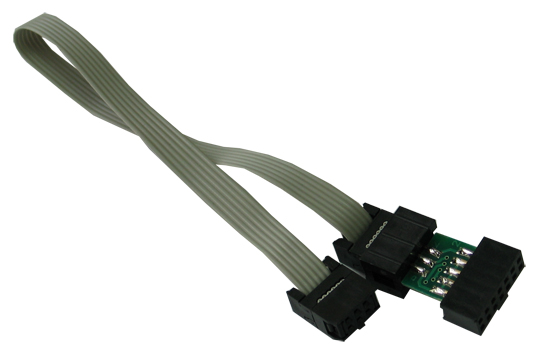
After some digging around it transpires that the 10-way ICSP header must use a 10-way to 6-way converter PCB to program ICSP with 6-way headers! Yours from Olimex for £2.00 less P&P.......you got to be F*@KING Kidding me.
Extras sold separately! Typical!
To make me feel more like a complete Burke, I found out the manual on the SUPPLIERS website was out of date compared to the Manufacturers copy, which gave me more information on what status LED's should be!

Let this be a lesson: RTFM - but make sure its off the Manufacturers website! That way its more likely to be up to date!

So with that fresh information, I was relieved that the LED's were correct (they change status meaning after firmware upgrade), but now knew I had another obstacle in the way! 

No dice Olimex, I ain't forking out more cash! I'll build my own! Dug around for some parts and came up with a homemade solution!

Header Converter


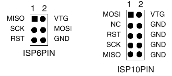
Using the diagram, I basically connected all the identical pins together on the 10-way to the 6-way, like below:
I quickly threw it on a scrap bit of strip board

You can't see it but I placed a dot near the middle pin on the 6-way to signify the place where the keying tab on the cable goes, so as not to connect it up the wrong way round.

Programming the Arduino through the ISCP, Take 2

I STRONGLY ADVISE YOU TO READ THIS SECTION CAREFULLY IF YOUR PLANNING ON DOING THIS, AS THERE ARE SOME VITAL THINGS YOU NEED TO KNOW!

It will be explained later, but when you program the Arduino with the ICSP programmer, it appears to over-write the boot-loader on the micro controller.

THIS MEANS ONCE YOU UPLOAD YOUR PROGRAM VIA ICSP, AND YOU TRY TO UPLOAD WITH YOUR USB CABLE AS STANDARD LATER, IT WILL NOT WORK.

I connected up the Arduino with an LED hanging off pin 13 and the ICSP programmer connected Via my homemade converter, I then tried to load the blink sketch as before, aaaanannnnnnnddddd.......(drum roll):
SUCCESS!!!

It worked! But I had then hit another snag!

I Tired uploading a different sketch to the Arduino and the IDE was acting like it wasn't there.
Typical fault of wrong port selected or not plugged in, or in this case no boot loader!
The only thing I could think of was that I had overwritten the boot-loader when I programmed the Arduino! Using the programmer connected to the same header on the Arduino again. I then proceeded to re-burn the boot-loader to the Arduino:

The programming was successful and managed to use it normally again.

Also if you getting this error on your Arduino, and you have tried ALL other solutions and still nothing, then AND ONLY THEN should you look at re-loading the boot-loader. Don't go spending 17 quid on an ICSP programmer and find out it selected the wrong serial port on the IDE!

So.... what Did I reckon?

Well the Olimex AVR-ICSP-MKII is one 1 of many ICSP programmers out there, and you get what you pay for.

Kudos on design for sticking it in a D-sub housing, but a must try harder on the manual.

Overall I'd say good purchase for beginner, and if you don't want to fork out for a converter then make one yourself like me!

Anyway, I have managed t get my head round on Programming boards with ICSP and the Arduino IDE. This should free up my arduino when it comes to strip boarding and prototyping my future designs

I'll be looking further into ICSP design considerations when prototyping up a project. Will leave that for another entry hopefully.

Laters!

Wednesday, 6 March 2013

Turbo Time! Strip down and Mod of Turbo Gauge

Background

I bought a Greddy Turbo Gauge off ebay a while ago it if in my Landrover. The engine is a 200TDI, which is a 2.5 Litre  Turbo Diesel.


However, When turbo's go, they go VERY badly and are expensive, so this gauge is more to check on how well it is rather than for tuning purposes. A new turbo is £200 for a second hand one and £400 nearly for a new one! A refurb. kit and rebalance is £100, so I'd rather catch it before it goes for a refurb. than when it goes and cough up for a new one! Observing a loss in boost pressure could be an indicator.

Test and Inspect

So i got this gauge a while ago and notice that the guy had cut the back-light wire off on it near to the nub practically. Of what wire I could clip onto, I stuck  12V on it and sweet-fanny-adams, no back-light!

I then got a mate to check the gauge worked, whilst I blew into the pipe inlet, needle moved when I belw so at least it's primary function worked!

I extended the wires on the back-light first, as this was an easy job, and plus I need to reference which one was positive.


Disassemble!

To quote a certain Mad Aussie Bloke (+EEVblog) :
"Don't turn it on! TAKE IT APART!"
I began to dismantle:
I undid the nut holding the inlet on the back of the turbo, in hoping to loosen something up. No luck! All I succeeded in was to knack up the needles default position. So this meant I had to cut off the crimped on collar holding the front screen in place.....I'll have to come back and think of a way to put that on later.

With the glass out and the nut on the inlet off, I slide the gauge face out of the casing, Inside was a circuit card with 2 blown filament bulbs soldered onto it (why, why would you solder a device that you know will blow and needs servicing to a PCB!) and on the back of the gauge face, what looked like the insides of a grandfather clock!
Old Skool Brown and copper PCB!

WHY! WHY, solder these on?! Use a F*@king socket!

Pretty Primitive when you look at it!

Inner Workings

After a closer inspection, I managed to work it out.

The thick bent piece of copper is a hollow and is connected to the inlet by a small piece of copper pipe. One end of the bent copper is soldered shut. The closed end of the copper is connected to an arm, the other end of that arm has a toothed rack, that moves a toothed spindle. The spindle is connected to the needle on the front of the gauge and a coiled spring, so the needle can return to its rest state.

When air pressure is applied to the inlet, it inflates the bent copper pipe slightly, this cause the bent copper to expand by increasing its radius (basically trying to straighten itself out!). This pulls on the arm which moves the needle.

There are a lot of small movements involved, that are scaled up to big movements (needle). It could be said that this is a mechanical amplifier!

I managed to reset the rest position of the needle by squeezing the the bend copper pipe slightly to run the rack off the spindle allowing the needle to move freely. Then just resetting the needle so that when the rack ran back onto the spindle, so that it rested as near the 0 mark as possible.

Modifying the PCB 

So the first thing was that stupid filament bulbs come off, with a hot soldering iron:

I had a couple of spare white LED's lying around at home. These will do to replace the bulbs.

Now a few calculations to work out the current limiting resistor:

I got the Vf & If from hooking one of the LED's up to a PSU with a low current Trip and carefully cranked up the voltage with the fine adjust:

So why have I hooked up the LED's in series? Well given that my input voltage is much greater than Vf of each LED, I can do it this way and only have to use 1 resistor.

"But you could do it in parallel, and not hack up the PCB as much!"
Yeh, but that's the wrong way of driving an LED, working below shows why:

Both solutions pull twice the current. Yeh I know its gonna be supplied by the landy's battery and alternator, but that's no excuse to be inefficient! The top solution is not good as I know these 2 LED's are not exactly from the same silicon die! Hence it can't be ensured that each LED will pull 10mA each, and as such their forward voltages will "fight" each other.

If you wan to drive more than one LED at a different current, then the second solution is more suitable.

The top Solution should NEVER REALLY be used!

With components sourced, I modified the LED's so they could be soldered on at the same height as the bulbs:

After some track cutting on and soldering of a few link wires, I got the PCB how I wanted it:

Testing

I set the Benchtop PSU as follows:
So this is basically simulated running off the battery, I set the current trip to the max current limit the LED's can carry, so I don't blow them in the event of a fault.I know they can carry more, but I designed them for 10mA, so more than 20mA, I know somethings VERY wrong!

Flicked power on a VIOLA! Not too bad!

And current consumption is near as damn it spot on to calculations!

So, cranked up the voltage to simulate the alternator running.

Flicked power on. Hardly much difference......

I did expect a current rise of this proportion, so all is as I expected.

So all in all, I'd say that was working properly!

Re-assemble

I popped the PCB back in its place:

Popped the dial back on and bolted the inlet to the back of the case. I then hooked her up for a showcase!
OHHH! Pretty!
You'll notice the bright spots on the dial, this means the LED's are too close to the dial, not the worst thing that could have happened!

That's good! But Have you knacked it by taking it apart?

Well, I  looked at the needle in the mirror whilst I blew into the inlet. The needle moved into the positive pressure range, whether by the right amount I don't know ( I blew to about the 0.4kg/cm mark). If this is wrong then I would think the spring needs adjusting.

The main thing that's a concern is how I'll get the glass cover back on now the collar is mangled! Super glue and a G-clamp is looking a likely solution.

Once I've sorted that, then its ready to mount on the centre dash console with another project I have in the pipeline....watch this space!