Tuesday 19 August 2014

MIG welder rebuild update and Welding Practice (on a budget!)

Update


So I managed to get a screen on the Ardu-weld (which I have now decided to call Ardu-MIG) doesn't look too bad and can update the info on the display on the fly when adjusting feed speed and gas delay. I am implementing a latch mode and possibly a stitch mode, but will see how that goes.

Welding Practice

Even though I could wax-lyrical about how welders work, I can't weld for jack-shit! This is apparent in the fact that I have tried to weld the steering guard back on big blue 3 times and 3 times I've driven back from a trail with it in the passenger seat! Still better than it catching a lift on an AA truck with track rod in your hand!

I thought I'd look up welding tutorials on YouTube and came across this guy: +ChuckE2009 
The tutorials are a little long winded, but its necessary as there are lots of factors to consider when stick welding (drag angle, angle to the work, electrode types). He does seem to know his subject well, young enough to remember, old enough to be experienced, good balance!

Budget!

I am basically learning how to weld with my means here! I am skint, have limited space and am willing to learn, so as you'd expect, my kit is not the best, nor do I have the facilities so I have to make it do!

So after watching the playlist, I thought I'd have a go, and managed to scrounge some scrap from a neighbor. bit of a buff up with angle grinder to remove rust and it was good enough.

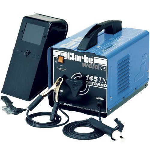
I already had a stick welder, which I manage to get for about £40 just a basic thing! It has seen better days, the electrode holder was on its last legs but the cabling was in good nick and the cooling fan did still work, so it was mostly cosmetic.

I bagged some electrodes at the local farmers auction! Probably 10kg of a mix bag for about £20! Bargain! Their quality couldn't be call on, as for all I know they could have been stored in a damp area, but they looked good, no signs of dampness!
Left to right: 2.5mm (unknown type), ESAB 30.25(?) 3.25mm, 6013 3.25mm, Stainless Steel 3.25mm
So for practicing I used the 6013 3.25mm as it suited the metal thickness I was using and was the only one I could identify from the welding tutorials!

So out in the Garden (after the kids gone to bed) I set-up my work space:
The reason I had to work outside the shed was:

  1. No welding within 3m of flammable materials - shed is full of bottles of various petro-chemical fluids from servicing vehicles, oh yeh and AND ITS A WOODEN SHED!
  2. Not enough room
  3. Ventilation - you need  a lot of ventilation when stick welding, the fumes given off are not nice!
I am aware that I am welding on a wooden board, but the the work is performed upon a large piece of scrap metal which make a good heat sink and only mildly scorched the board. As an extra safety addition I had a fire extinguisher on standby!

I didn't have a chipping/slag hammer, but the back end of a claw hammer did the trick. I do have a welders mask  which I bought new for about £15, just a flip down thing with a flipable lense. I also had:
  • a wire brush, to clear away loose slag
  • an angle grinder to cut and clean metal
  • some ear defenders - for when I'm using the angle grinder
  • some tough garden gloves I use when using the chainsaw
  • a piece of box section - I used this to rest on

Sparks Fly!

I set the amperage as per the ratings on the side of the box of sticks and the silk screen on the welder:

I measured the bare end of the electrode by eye with a steel ruler and came out to be about 3mm - so I took the size up for 3.25mm and wound the dial on the front till the pointer on the scale came to 3.25mm or about 115A

First off I decided to put a pad of beads down:
This was to get a feel of things, practice putting and arc down and generally observe if I was moving too slow or fast and if my arc was too long or short. As the pad got warmer I back the current off a bit by about a few amps, I couldn't tell really as there wasn't any scale to go by!

I decided that I was going too fast for the first 3 beads so by the 6th bead I was happy that I'd got my drag speed dialed in. Drag angle appeared to be ok and arc length was bang on.

After a bit of practice I then moved onto a fillet weld and then a triple pass fillet weld. I first tacked up 2 pieces of metal so one was perpendicular to the other:
Then began to weld my single pass fillet weld on one side:
For a first try its not too bad! I seemed to be moving too fast at the start, not enough cut in the middle and improved a bit toward the end.

I then did a multi-pass on the opposite side:
Hmmmm - keep practicing I guess! The light at this point was fading and I was getting thristy - dehydration is not a good thing when trying to learn new things!

Lessons Taken

Well I am better than before and I have learnt quite a bit more than I did, however there are still more techniques to learn (lap weld, open root, vertical up and overhead)

Also my kit did not fair well! The electrode got REALLY hot by the last weld! after taking it apart I found the contact between the cable and holder was tarnished and the grip had melted!! I took it off and ordered a new one for a a Murex stick welder - rated at 400A and much better contact material with brass cable clamping!

My gloves where not thick enough and found out they had holes! not good! ok if your operating a chainsaw, but not for welding! So I order a set of good welders gloves. The mask faired well too!
Old glove to new gloves; new electrode to old and mask
 Also, and I am a burk for doing this, I thought I wouldn't be long and welded in just a t-shirt! Bad idea, I got colossal sun-burn on me left arm! Welding arc's emit a fuck-ton of UV radiation! Please make sure you have a long sleeved top on if your doing this! Ideally one that's old! either that or wear sun-screen!

More practicing will follow soon and maybe another update on the Ardu-MIG!

If you have any comments or pointers on my welding, feel free do so, I'd be much appreciated! And may thanks to +ChuckE2009, keep up with the videos dude! Helping a lot!


Thursday 31 July 2014

MIG Welder rebuild update

If you don't know already, I've been busy.....bouncing baby #2 arrived in June! Her name is Ferne. All is well with her and muumy!

So plodding on with this MIG welder (kindly donated by +Jezzmund Tutu's dad. Cheers Mark!), I managed to knock a milestone down: I have managed to develop a working system on the Arduino, with a development board I knocked up!

What I'm Aiming for

I basically want to try and run this, knackered, beat-up, SIP Ideal 180 Mig Welder, by replacing the electronics (as shown ) with my own, more modern and compact system, based around the same system as the Arduino (Atmel ATMEGA328P), with ability to upload an Arduino boot-loader and then use a serial cable to upload programs.

Electronics as it stands are shot, keeps blowing the fuse to the board, I believe there is a short on the rectifier for the motor control circuit. I never liked the way these things worked, so more the reason to design my own!
Proper old-skool electronics! who needs micro controllers!

All this will be stripped out, but am leaving the connections and wires to solder to the new board

Plenty of functions for a MIG, including latch trigger mode and stitch mode with duty adjustments. I'll be recycling the pots and rotary switches.

Basically the same way as done on Arduino, Stripped down and instead of a USB to serial circuit on board, use a USB-Serial Cable, available from most electronics hardware suppliers. Similar to what's done here: Nanino.

I want it to have all the basic functions of a MIG welder: Gas delay, Wire Feed control, Wire-Inch. The welder is a Conventional type, which means it has a HUGE, tapped, step down transformer, and a selector switch on the front to adjust the welding voltage (CV welding explained Here - Wikipedia on welding power supplies). As such, I don't need to worry about controlling the welding current and voltage from the electronics, just the gas and wire control.
Pretty beat up! Confident its just cosmetic! The number in the model name usually indicates its max current.

Left to Right: Voltage adjustment, "EARTH" clamp connection MIG/Spot welder selector, 3-Phase connector (dunno if its in or out?)
I did think about having a weld mode selector for stitch mode, stitch period on & off and latching trigger but I thought to start simple and then fit mode selections later.

Dev. Platform

Schematic - NB trigger button is separate on breadboard
Setup

The board is nothing special. Just a couple of relays with LED's. Relays are driven off 5V (as specified) by some transistors which in turn are driven off the Adrunio. Screw terminals allow easy fitting/removal of the wires to and from the Arudino and also from the bread board.

The  Inch button is located on the board and the trigger button is on the bread board with a bit of de-bouncing. I found a small motor so I could test drive the motor circuit I proposed to use. The motor so small and light that the solid core wires I soldered to it can hold it in the air!

I used 2 Trim-pots as gas delay and motor control. The motor driver circuit is quite simple too: the MOSFET (Q4) is constantly driven by a PWM signal from the Arduino. The relay (RL3) in its Normally Close position, shorts the motor out through a very low value resistor (R7). When the relay is energised, the pole is switched to the 12V supply and Q4 has some power to drive the motor with. Simple and effective.

Some Theory

R7 essentially holds the motor. If you tried to turn it by hand, it won't budge as all the current generated by the motor tries to flow through R7, essentially a short circuit. 

You ever tried to generate a voltage across a short circuit? Its bloody hard! 

If R7 were 1K for example, it would allow the motor to be turned by hand a little and the current generated from the  motor would give rise to a small voltage across it (ohms law).

So in the situation where the motor is running and then you remove the power, the motor will slow down over a short period of time. This is not desirable if its feeding your wire for welding as it could get stuck to the work! you want it to stop instantly!

So by shorting the motor through the high wattage, small value resistor, all the current generated in the field of the motor windings from the momentum of turning a big spool of wire gets dissipated as heat in the resistor and the motor will stop a damn-sight quicker! exactly like the brakes on a car!

I've seen similar things done with Triacs and long pieces of track whilst repairing boards from MIG welders. They are prone to blowing the tracks and the braking Triac alot! So if your MIG welders does not stop feeding wire when it should, that's the problem!

Arudino Sketch

/*
Ardu-weld - Arduino based welder control board
Author: Tronicus
Date: 13-May-2014
Ver: 1.0
web: tron9000.blogspot.com
*/

//files to include
#include <Wire.h>
#include <stdlib.h>

//definitions & declarations
#define in_TRIG 2  //trigger pin
#define out_WS 3  //Motor speed control pin
#define out_GAS 7  //Gas relay control pin
#define out_CON 8  //Contactor relay control pin
#define out_BRK 4  //Motor brake relay control pin
#define in_WF 12  //Wire Feed button input pin
#define in_DIR 5  //Wire feed direction control input - later version of development
#define out_DIR 6  //Wire feed control output - later version of development

//Variables
int WS_MIN = 20;  //Minimum wire speed
int WS_MAX = 255;  //Maximum wire speed
int GDEL_MIN = 10;  //Minimum gas delay time
int GDEL_MAX = 1000;  //Maximum Gas Delay time
boolean welding = false;  //flag to indicate has been or finished welding

//*********************************************Main Program*******************************************//

//setup
void setup() 
{
  pinMode(out_WS, OUTPUT);
  pinMode(in_TRIG, INPUT);
  pinMode(out_GAS, OUTPUT);
  pinMode(out_CON, OUTPUT);
  pinMode(out_BRK, OUTPUT);
  pinMode(in_WF, INPUT);
  pinMode(13, OUTPUT);  //LED Alive pin
  digitalWrite(13, LOW);
  //Serial.begin(9600);
}

void loop() 
{ 
  while(digitalRead(in_WF) == LOW){inch();}  //check to see if Inch button is pressed
  while(digitalRead(in_TRIG) == LOW){weld();} //check to start welding
  if(welding == true){dis_weld();} //if you have been welding: disengage
}

//******************************************Welder control******************************//
/*
Code for controlling the welder (Wire feed, contactor, gas solenoid, trigger type) goes here
*/
void weld()  //starts welding welding
{ 
  welding = true;  //now/was welding
  digitalWrite(13, HIGH);
  digitalWrite(out_GAS, HIGH);  //turn gas on
  //Serial.println("GAS ON!");  //uncomment as neccesary
  digitalWrite(out_CON, HIGH);  //close contactor
  //Serial.println(welding);  //uncomment as neccesary
  feed_wire();  //feed wire
}

void inch()  //feeds the wire
{
  while(digitalRead(in_WF) == LOW)
  {
    feed_wire();
  }
  digitalWrite(out_BRK, LOW);  //turn on brake
}

void feed_wire()  //function that feeds wire whilst allowing speed adjustment at same time
{
 digitalWrite(out_BRK, HIGH);  //Release Brake on motor
 analogWrite(out_WS, map(analogRead(0), 0, 1023, WS_MIN, WS_MAX));  //set the output speed of feed motor
}

void dis_weld()  //stop welding and finish with gas
{
  int del = map(analogRead(1), 0, 1023, GDEL_MIN, GDEL_MAX);
  boolean FLG1 = true;
  while(del > 0)
  {
    while(FLG1 == true)
    {
    digitalWrite(out_CON, LOW);  //turn off current
    digitalWrite(out_BRK, LOW);  //apply brake to motor
    FLG1 = false;  //make flag false so this isn't done again
    }
    delay(1);  //delay 1 ms
    if(digitalRead(in_TRIG) == LOW)  //read and check that trigger has not been pressed
      {
        del = 0;
        weld();  //if so weld
      }
    //Serial.println(del);
    del--;  //decrease del
  }
  digitalWrite(out_GAS, LOW);
  welding = false;
  digitalWrite(13, LOW);
}

Breakdown of Program

so in the main loop(), I'm constantly checking the trigger and inch switches for a change in state and then calling the appropriate function when one of those switches are pressed.

When the inch button is pressed it just calls the function to turn on the wire feed motor at the speed set from the analog input, mapped against the defined max and min wire speed, this only happens while the inch button is pressed. once the inch button is release it engages the brake for the motor.

when the trigger switch is press it calls the welding function: this function first sets a flag (in the form of a Boolean variable) to acknowledge that welding has/is happening/happened. It then turns on the gas solenoid output and then the contactor (which puts power to the lance for welding) and then starts to feed the wire at the mapped speed from the analog input. It does this till the trigger is released.

Once the trigger is release, it returns to the Loop(). It then checks that the welding flag has been set, if it has then it must start the welding disengage function. 

This function basically reads in the value off the second analog input to determine how long it needs to leave the gas on for, sets another flag to indicate it has turned off the contactor and apply the wire feed brake, and then checks at 1ms intervals if the trigger has been pressed whilst the gas is left on.

If the trigger has not been pressed during this interval, it decrease the integer: del. When del = 0, it turns the gas off and set the welding flag to false and returns to the loop(). If the trigger has been pressed, it clears the timer variable (int del) and returns to the welding function.

And the results can be seen for themselves:

As it can be seen, I Press the inch button and only the motor turns. I press the trigger and the Gas (green LED), contact (red LED) and the blue LED (sequence indicator, tells me when its stopped doing things) come one and the motor turns.

When the trigger is released the gas LED stays on for a while longer. I adjust the Gas pot and the gas on interval is now a lot shorter (practically 0).

I then adjust the motor speed pot from full, to half way and then minimum, and the motor speed responds accordingly. Notice that the motor recoils a little, that's the brake circuit kicking in!

Sorry I couldn't show the speed change on the fly, but I had to hold the camera!

Expansions and Extra features

So like I said before I could have included and stitch function and a latch function like the original, I might yet include a latch function.

I was also thinking of including a motor direction switch for inching only, so you can spool the wire back a bit if required.

I would really like to add one of the LVK204-25 LCD screens on it to display current and power. I have a few analog and digital inputs left and it'd be rude not to use them!

Problem with measuring current is I need a shunt capable of taking high current (most likely up to 180A), which in this case would be a brass bar with enough metal shaved off to give the right resistance. Seen them before, will have a look around. Also with measuring shunted currents and voltages up to 5x higher than the mirco-controllers supply voltage is isolation. I've seen monitoring circuits in welders go really badly when things let go!

Anyway, food for thought, until next time.

Tuesday 29 April 2014

NES Zapper Hack

So after a Clear out of the shed (freeing up ALOT of space), I found Some old Nintendo Controllers and a Zapper. The Console had long since gone after I tried to repair it and got nowhere.

After a quick browse on ebay to see what I could get them, I found that it's flooded with the buggers and any that do sell don't go for a great deal anymore; not worth the insertion fee or postage.

So I had a brainwave, turn it into a toy!

I had the idea of changing it so it 'fires' a beam of light out the end with a pull of the trigger!

A Laser source is out of the question here! I don't want me lad going blind! Also I didn't have one in my spares box...

But I did have a clear, 10mm, RGB LED wired up already from another project, so that'd do! I also had a PP3 (9V) battery plus a clip for it, so I'd base the design around that power source.
NEZ Zapper with Lead cut off, Hugo wanted to play with it, and it was a trip hazard!

Tear Down

The Zapper is quite simple in construction, all you need is a suitable Phillips or Cross-head screw driver:
3 screws hold the grey fascia to the orange body..

Then 2 screws on the handle and 2 smaller screws on the foresight & barrel end allow you to get inside

A Look at the Innards!

  1. Focusing Lens - plastic, focuses the image on the screen to the photo diode in 3.
  2. Ferrite Core - 2x half cores taped together to form a cylinder, used for balancing the gun's weight
  3. Photo-detector Circuit - has a Photo diode and associated circuitry
  4. Trigger mechanism - houses a switch connected to the Photo-detector Circuit
  5. Brass coloured weight - as with 2. its used to balance the gun

Basic Overview of Operation

So when you press the trigger, the closing of the switch is a signal to the Photo-detector circuit to capture the image on the screen, which is focused on a photo-diode. 

This information is then passed to the console via the lead and the NES processes this information to decide weather you hit the duck (I'm assuming you're playing Duck Hunt), hit thin air, or if you're shooting the giggling dog cos you suck! Don't lie, you have done that!(http://people.ece.cornell.edu/land/courses/ece4760/FinalProjects/s2003/lbb23/duckhunter/hardware.htm)

Get Cracking!


So before I got too far in, I double checked the switch on the trigger assembly to make sure to worked and its configuration. Turns out it is a Normally Open (N.O.) switch and closes when the trigger is pressed. However it is only closed for a small period of time, its essentially a mechanical one shot timer.

Now armed with information on what I was dealing with, I drafted up a circuit diagram:
A decided to go with a blue LED for the colour of light beam. Typically a Blue LED has a forward voltage of 3V, and I wanted it really bright, so chose a current of 30mA, a bit overkill, but within limits.

So from these requirements I needed a current limiting resistor of about 200OHMs - no 200OHM resistors in spares box so went with 2x 120OHM resistors, thus giving a current in the LED of 25mA - ok that'll do!

C1 is to provide some sort of extension of the duration on which the light beam stays on for, I didn't bother with in depth calculations here with regards to current draw from cap, I just did a simple t=RC calculation.

I chose t= 240ms, so C1 must be somewhere in the region of 1000uF. <rummage in parts box>.........BINGO! 1000uF @ 10V (oohh close to max voltage of circuit but should be within limits), this gives a delay of 250ms

I unscrewed the 3 larger screws holding the trigger assembly in place, disconnected the lead out to the NES from the circuit board and cut the wires on the switch to leave the trigger assembly by itself:


I then refitted the trigger assembly back and offered up the main parts of the design so I could see what needed hacking off:

The holder for the Brass weight and one of the screw mountings/fittings on the handle had to be removed with a Dremel and the same on the opposite shell: the mating mountings and fittings. I judged that only one screw would hold the handle part of the zapper together OK.


After a bit of assembly, dis-assembly and routing out I managed to get the battery to fit perfectly. The battery has to be fitted before fitting the trigger assembly. Hopefully the battery will live long enough so that swapping it out is not a common occurrence.
I closed up the 2 halves of the zapper to make sure battery fitted OK with the trigger assembly in place. Like a glove. I was also right about the screw mount I routed out, its happy with just one screw in the handle.

Now I could begin wiring up.
Soldered the Positive terminal of battery to one side of switch. Then soldered up LED, resistor and capacitor and tested with battery:
Resistors are covered in heat-shrink as are bear wires on capacitor leads

It Works! Knew it would...

I then soldered the black lead of LED assembly to Negative lead of the battery clip, hooked it up to the battery for a final test before fitting:
The LED does fade off rather than shut off after a delay, which is what I expected. still the effect is still good.

I'd also like to point out that you should heat-shrink over solder joints or at least us insulation tape.

Then it was just a case of fitting everything back in:
 I decided to fit the LED into the barrel weight, it holds it in place better and taped down the wires to the shell for additional support whilst I tried to screw it back together. I also tapped over the now redundant screw hole in the other half of the zapper. I also fitted the lens back in, which is not shown in the above picture.

Taped over screw hole

Viola!

Test of Finished Hack


Well its bright! The overall original aesthetics have been retained and the blue light looks cool! Also the barrel glows when fired, making it look like its overheating!

Not bad for a Sunday afternoons work! Built just in time for sonny-jim to wake up from his afternoon nap and test it!
What does this button do?

Improvements/Design flaws

Well I did originally plan to find a knackered Buzz Lightyear Doll - with the the arm laser button, and gut it for the laser sound module. That could be an add on if and when I find one, so will trawl the local car-boot sale.

I did also think of using a 74595, shift register IC so that with each pull of the trigger, the beam changes colour, that would also be cool, but will the circuit it fit inside the zapper?

Also; having a capacitor that gets switched directly to the battery is not really good design. If you think about it: a large capacitor looks like a short circuit to a power source. At the point of the switch closing, the capacitor is going to yank the battery for all the current it can get for a fraction of a milli-second, this could stress the battery.

The switch in the trigger assembly may have a Normally Closed pin as well.If so then I can use it as a toggle between charging the capacitor from the battery and discharging through the LED. This means cracking the trigger assembly open to check for the extra pin on the switch. I was avoiding this as I didn't want to open it up and any tensioned springs to pop out!

Thursday 20 March 2014

Fluke taking the Mickey?!

I just found this article on +HACKADAY :
http://hackaday.com/2014/03/19/multimeters-without-a-country-flukes-broad-trademark-bans-yellow-multimeter-imports/

It basically outlines the RIDICULOUS blanket block on the import of SparkFun's DMM, because - get this: It has a Yellow frame with a Black face!
Sparkfun's hobbyist DMM
Fluke 17B - looks slightly similar 
Apparently: Fluke own this colour scheme as a trademark, and as such Sparkfun have supposedly "infringed" on this trademark and customs have seized them coming into the states.
Customs letter to Sparkfun

Now I'm not a law expert...BUT THIS IS ABSURD!

I'm sure Fluke are not at fault here, It's probably the over zealous customs officers following the letter of the law a step too far! I doubt they know what a DMM does let alone define a Fluke from a non-name brand! Seriously - a lack of knowledge is not an excuse to rule over someone else's business! SHAK' YER 'ED U.S. CUSTOMS!

But also: trade marking Yellow and black! WTF?! who else you gonna block cos they used yellow and black? JCB? CAT?

Oh we can't let this in!
Why Not?
Cos its black and yellow, its got the same colour scheme as a wasp!
......its a BLOODY DIGGER!


UPDATE - 21/03/2014

Fluke have been helping Sparkfun out with the loss of their multimeters by giving them some Flukes to sell. Nice one Fluke. 

As I expected: US customs are being, well lets call a spade a spade here: a bunch of dicks.

Wednesday 19 March 2014

A Blast from the past - Arc Blast that is - MIG welder restore

So, I probably mentioned  that I used to repair welding equipment...no? ok: I USED TO REPAIR WELDING EQUIPMENT.

Well ever since I got a Landrover trails vehicle, I've needed to carry out repairs, mostly to the steering guard, since this bears the brunt of all low lying obstacles: tree stumps, rocks and the like.

I bought a stick welder thinking that would do the job: Its a 145A Clarke Stick welder, that was in good nick when I bought it for about £40. I then went to the local farmers auction and managed to bag more sticks than I would ever need for about £20!
Clarke 145A Stick welder, in better nick than mine!

The good thing about this kind of stick welder is that there are VERY few components and cheap to run. It is essentially on over-sized step down transformer with an adjustable center tap-off and a either a heavy bridge rectifier or no rectification at all. Some older versions of this design are submerged in mineral oil (and I've heard from the old skool they are BETTER than modern designs)
Typical Adjustable stick welder, this is a schematic from a Lincoln AC-225 stick welder
However; this has its limitations. For one: you have to replace the sticks when they run down, and another is its flexibility. Welding with a stick welder, on your back, under a Landrover is full of pitfalls! If the hot weld starts to pool, it eventually turns into a hot, molten drip of DOOM! And you have to take drastic evasive action, usually meaning you clonk your head on the diff

Amongst other things, the finish: stick welding leaves a lot of slag, which you have to brush off. 

Replacement?


Anyway I got donated a MIG welder from a friend. I had offered to fix it for him and he had giving me the control box out of it to look at to start with, and christ its old skool! LM324's, triacs and more 4000 series logic than you can shake a shitty stick at! I started to fix it, but I picked up something else and forgot about it, it wasn't an urgent job fortunately as he had another welder. So he decided to give it to me, and turned up a trail event and dragged it home.
Typical MIG welder


Its pretty beat up, its seen better days, and it "doesn't work" (we'll see). I was told that it would turn on, you could feed the wire but no power, as the contactor wouldn't close. The contactor had been replaced but still didn't close, which means its the drive circuit probably. I have fixed boards like this before and they are pig! alot of signal sniffing and 9 times out of 10 its either a leaky diode, or leaky transistor, or leaky triac or a leaky output on a logic gate or op-amp.

Welder electronics are like people - when they get old, they get more leaky!

And with good reason, they get a lot of hammering and some of the welders I have fixed have: Made in West Germany printed on the side! so quite old about 30 odd years or so!

Plans

I plan to keep the major components: the wire feed motor, contactors, gas solenoid and existing transformer; and replace the drive electronics with an arduino based equivelent.

I'll be employing relays to control contactors and solenoids and a high power MOSFET to control the wire feed motor.

The whole lot will be plonked onto strip board and fitted back into the existing electronics box.

Wire everything back up, beat a few panels back into shape & a lick of paint and jobs a good-un. I'll aslo need to purchase a new lance too.

Right: best clear the crap out of the shed then!

Monday 17 March 2014

Stripping the Swivel on my landy

This weekend I managed to fit the Swivel housing back on my Landrover (YEY a post about something other than electronics!)

I had done it before when I first got the vehicle. This was because at about 40mph a horrendous wheel wobble manifested itself when driving on standard road tyres! After changing the pan-hard rod bushes & Hub bearings, I did a quick overhaul job on the swivel housings and then the problem cleared.

However, a year down the line and the passenger side started leaking a mixture of EP90 and CV joint grease on the driveway......something not right and I had clearly not done a good job.

This lead to finding some useful advice and an glimpse into this vehicles past....

Do Your Research!

For those of you unfamiliar with parts of a Land rover - the swivel housing is located on the ends of the front axle:
From Landroverclub.net
And here are some exploded diagrams of the housing for my axles, courtesy of AllBrit (list of parts their website, follow the links under each pic)
The Swivel housing
The Swivel joint


The housing fits over the joint. Inside the housing is a CV joint (#2 on the swivel joint). This enables the drive from the differential to be transferred to the hub/wheel, via the half-shaft (#1 on the swivel joint), whilst allowing the hub/wheel to be steered.

I also did a bit of a search for guides on how to service/overhaul these swivel joints and came to a favourite channel of mine on youtube: Landrover Toolbox Videos  

If you look though his playlists, you can find an entire playlist dedicated to replacing the swivel housing in detail and from someone in the know, also a load more on tool reviews and tips & hints; mostly Land Rover related +Land Rover Toolbox Videos

I then ordered a swivel joint overhaul kit: DA3164P, from Paddocks and made a start.

Stripping & Re-build

On the bench
After taking the wheel off and freeing the track-rods, I undid the 7 Bi-Hex bolts holding the swivel joint to the axle, allowing me to pull the hub, housing and half-shaft out all in one go, to then take to the shed and start stripping it down and cleaning all the parts and inspecting them individually.

One thing I noticed when taking the half-shaft out was no EP-90 followed it out or leaked out when taking the bolts off! Probably cos it had escaped onto the driveway! A sure sign the seals had probably not been fitted properly!

After stripping the whole assembly down to its individual components and cleaning them in paraffin, I found a few errors I had made:
  1. I had left the old gasket from before, for the bottom pin on the housing!
  2. I had not put grease on the inside edge of the swivel housing
  3. I had totally pre-loaded the housing incorrectly!
  4. All surfaces for gaskets were not cleaned properly or at all.
Well that's what you get for a rush job! lesson learnt!

After I had cleaned up the parts I gave the surfaces where there would be a gasket (Housing face to stub axle, the face where the swivel joint joins the axle, and the face of the stub axle)  a pass with a Stanley blade, a scrub with a wire brush and then a finish with some wet/dry paper to clean them up proper.

Using a vice to hold the swivel ball, I began to pre-load the the housing as per the video. Once happy with the pre-load I fitted the the axle seal, and the oil seal. then moved the whole assembly to the vehicle where I cleared the old gasket & gunk for the axle end and built the rest up on the vehicle.

All new gaskets were fitted with some sealant on the mating surfaces.

Fresh pack of one-shot in the filler for the housing and some fresh grease and seals in the hub & bearings and job's a good'un. No leaks so far, but will see after I top up diff with EP90.

What was learnt

  • Pre-loading the housing bearings properly is vital!
  • Clearing the crud of mating surfaces helps
  • Greasing seals helps ensure a good seal to keep unwanted muck out and keep lube in.
  • Taking the time to clean your parts aids to a doing a job properly!
Also found out that the front axle is of a series 1 discovery:

This is not surprising really, the vehicle was trailed a lot before I got it, so it's more than likely that they were swapped due to damage.

Unfortunately, I damaged some of the brake lines to the calipers whilst trying to re-fit the assembly, another job on the list then!

HEY-HO!