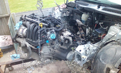
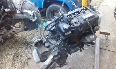
Its not as bad as you think. Most of the job involve some lateral thinking, careful disassembly, a clean work surface (an old towel mopped up leftover oil) and careful recording and keeping all removed parts laid out in comprehensive way.....(yeh right!)
Homework
Firstly its good to get an idea of how a gearbox works:The next video explains briefly how front wheel drive transmission works and +Engineering Explained does draw a pretty accurate depiction.
Disassemble
To start: I remover the aluminium cover off the back of the gearbox.Here there were 2 gears held onto the shafts with 2 staked nuts. The left shaft is the input shaft, the right is the output shaft that drives the diff. I removed the staked nuts by wedging an old towel between the gears and then using a 32mm socket, running the bolts off with an impact wrench. This stripped the indent in the nut and came off pretty easily without stripping the threads.
Then removing the gears I kept the dog-teeth gears and together with them placed them in the ali casing - this was to remind me that this was the parts that go under it.
After that I removed the bolts that held the bell housing to the gearbox housing - 17x 10mm head hex bolts. I then tried to lift the housing off but couldn't. After trying to find a locking clip inside the box between the gap of the bell housing and gear housing, I realised that the 2 bearings under the 2 gears I removed earlier had captive clips held in place with 2 torx head bolts each....and we're torqued up to the hilt!! A cheater bar on a 1/2 drive trox bit loosened it off!
Once the 2 clips came off the gear housing slipped off revealing the glorious tower of cogs!
The forks that push the dog teeth gears to select gear are held onto the selector rod with roll pins. Some of these had to be tapped out enough to release the rods so the gears could come out but with tapping it all the way out to keep parts together.
After some jiggling it all came out, the reverse gear lifting arm came out by just pulling a pin and lifting it out. The gear itself is on a loose shaft that just lifted out.
The races were tapped out of the bell housing and gear housing. These were not in that tight and came out with a few swift strikes of a hammer on a drift. This had to be done to get the part number off the races. Here is a video of a brief look at the insides:
Diff was now ready to receive the new bearings.
The bearings went back on with using a press or even dropping the diff in liquid Nitrogen, which was offered by works physics dept! A couple of deft taps with a hammer on the correct size socket and they were refitted! Fitting the races were equally easy, using the old races as a drift.
Assembly
Put the diff back in and put the plate back on. By chance I found a little metal nub with a spring in it. This was the reverse locking pin! It must have fallen out when I bashed the races out, so be aware of this! I popped this back in the recess underneath the reverse gear selector pivots.Torque down all the bolts as hard as you dare, the housing is only aluminium, too hard and you risk stripping the threads, too loose and the plates not seated enough. For the Blue headed bolt, a little less torque than the others - I have no torque specs unfortunately, but they were on really tight when I took it apart, blue one less so.
Getting the Gear towers back in was a ballache. The selector rod from the linkage had to be disassembled and then all the gears all re-fitted and then the selector mechanism re-assembled.
Then you realise that you left off the reverse gear....right after you have re-tapped all the roll pins!
It takes some time, so be patient and test as you go: move the selector lever to verify (push it in and out and left and right in all combinations): if it looks, sounds and operates right (take note of the selector lever position below this is the general orientation it should be fitted).
Once all the gears where in and looked in the right place and moved the selector about to go through the gears I put a bead of silicone around the whole outside of the mating surface:
I slid the gearbox housing over the top and tried to squarely plonk it down onto the mating surface. some silicone did squeeze out, but that's normal. Again take the bolts that were holding the bell housing to the gearbox housing and torque them up on opposite sides rather than going round so that they are mated evenly.
Replace the 5th gear assembly and selector fork, replace the C-Clips and tighten the torx bolts to hold the gear shafts in place. Tap in the roll pin to hold the selector fork for 5th gear in place. Fiddle around with the selector lever to double check that it all works good.
Next: I stuck a towel between the teeth of the gears and spin the staked nuts back on. I tighten them till the section that was dented is back in roughly the same position where the flat spot on the threads are, don't just position them, they have to be tight! I took a blunt chisel and smacked the nut so that it deformed back into the flat spot. A final test spinning the drive shaft with the impact driver at slow and changing gear confirmed that it was working correctly including reverse gear!
PHEW!
I wouldn't take this way of doing it as gospel, admittedly I did cut some corners: I should have got new staked nuts, but they did the trick:
Refitting the engine
 |
| Long slog to driveway! |
With the engine back in the barrow, it was back down the garden and to an awaiting engine bay! Getting the engine back in was actually quite easy, the only hard part was trying to get it to line up with the mountings, but once you have it, its not too bad.
Cos I'd marked up all wires, that too was an easy task. I had it fitted and hooked back up within an afternoon!
Before I refitted the airbox and battery, I refitted the drive shafts and filled it back up with oil through the breather (its a funnel like plastic thing on top of the gearbox, which you can take the cap off): it takes 2 litres of MTF-94, don't go to halfords for it, they'll just look at you blankly! get to a place like Andrew Pages or similar mechanics supplier. It takes a with to fill it up through the breather, but cos its a funnel and of its position, its convenient!
Also reconnect the linkages for the gears, if you remembered how they went on. it should be apparent as they will struggle to fit if the wrong way. Check before you put the battery box back on: 1st, 2nd/3rd,4th move the selector front and back, selecting between 2nd & 3rd & 5th should move the selector up and down.
Battery box back in, air box back on, ECU hooked back up and battery hooked up, I refitted the radiator and some of the lights and horns: time for a start up!
So did I fix it?
Well there is good news and bad news:
The Good:
- Engine started first turn! mint!
- Clutch worked, 1st, 5th & reverse took some effort to go in, but it changes gear like a treat now, much smoother!
- After realising I had seated the linkage cables in the forks incorrectly (the metal clips on the boots should sit in the forks) that problem went.
The Bad:
- The problem is still there! BOLLOCKS! but its no worse than before this job!
- I had to hack the exhaust back on cos I took a grinder to one of the bolts that were rusted up. The bolts on the tail pipe are captive, so I had to grind the surface where the cut bolt had been flat and drill a hole and use a nut and bolt with a spring washer. I'm not getting gassed, but it's blowing really bad!
- replacing the belt tensioner did nothing - it still squeals! So I suspect and incorrect belt fitted!
So I'm essentially back to square one! The only other thing is the the input bearing in the gearbox! If it is then I may as well just buy a kit and do the whole lot, but at £120, its money I don't have, but would be lot more if I got a garage to do it.
But hey! Least I know what to do now!


