Thursday 20 March 2014

Fluke taking the Mickey?!

I just found this article on +HACKADAY :
http://hackaday.com/2014/03/19/multimeters-without-a-country-flukes-broad-trademark-bans-yellow-multimeter-imports/

It basically outlines the RIDICULOUS blanket block on the import of SparkFun's DMM, because - get this: It has a Yellow frame with a Black face!
Sparkfun's hobbyist DMM
Fluke 17B - looks slightly similar 
Apparently: Fluke own this colour scheme as a trademark, and as such Sparkfun have supposedly "infringed" on this trademark and customs have seized them coming into the states.
Customs letter to Sparkfun

Now I'm not a law expert...BUT THIS IS ABSURD!

I'm sure Fluke are not at fault here, It's probably the over zealous customs officers following the letter of the law a step too far! I doubt they know what a DMM does let alone define a Fluke from a non-name brand! Seriously - a lack of knowledge is not an excuse to rule over someone else's business! SHAK' YER 'ED U.S. CUSTOMS!

But also: trade marking Yellow and black! WTF?! who else you gonna block cos they used yellow and black? JCB? CAT?

Oh we can't let this in!
Why Not?
Cos its black and yellow, its got the same colour scheme as a wasp!
......its a BLOODY DIGGER!


UPDATE - 21/03/2014

Fluke have been helping Sparkfun out with the loss of their multimeters by giving them some Flukes to sell. Nice one Fluke. 

As I expected: US customs are being, well lets call a spade a spade here: a bunch of dicks.

Wednesday 19 March 2014

A Blast from the past - Arc Blast that is - MIG welder restore

So, I probably mentioned  that I used to repair welding equipment...no? ok: I USED TO REPAIR WELDING EQUIPMENT.

Well ever since I got a Landrover trails vehicle, I've needed to carry out repairs, mostly to the steering guard, since this bears the brunt of all low lying obstacles: tree stumps, rocks and the like.

I bought a stick welder thinking that would do the job: Its a 145A Clarke Stick welder, that was in good nick when I bought it for about £40. I then went to the local farmers auction and managed to bag more sticks than I would ever need for about £20!
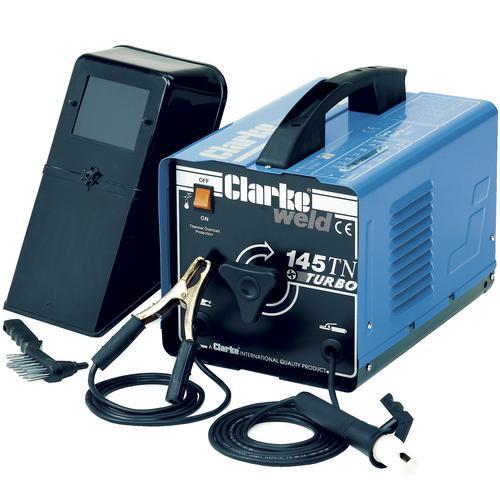
Clarke 145A Stick welder, in better nick than mine!

The good thing about this kind of stick welder is that there are VERY few components and cheap to run. It is essentially on over-sized step down transformer with an adjustable center tap-off and a either a heavy bridge rectifier or no rectification at all. Some older versions of this design are submerged in mineral oil (and I've heard from the old skool they are BETTER than modern designs)
Typical Adjustable stick welder, this is a schematic from a Lincoln AC-225 stick welder
However; this has its limitations. For one: you have to replace the sticks when they run down, and another is its flexibility. Welding with a stick welder, on your back, under a Landrover is full of pitfalls! If the hot weld starts to pool, it eventually turns into a hot, molten drip of DOOM! And you have to take drastic evasive action, usually meaning you clonk your head on the diff

Amongst other things, the finish: stick welding leaves a lot of slag, which you have to brush off. 

Replacement?


Anyway I got donated a MIG welder from a friend. I had offered to fix it for him and he had giving me the control box out of it to look at to start with, and christ its old skool! LM324's, triacs and more 4000 series logic than you can shake a shitty stick at! I started to fix it, but I picked up something else and forgot about it, it wasn't an urgent job fortunately as he had another welder. So he decided to give it to me, and turned up a trail event and dragged it home.
Typical MIG welder


Its pretty beat up, its seen better days, and it "doesn't work" (we'll see). I was told that it would turn on, you could feed the wire but no power, as the contactor wouldn't close. The contactor had been replaced but still didn't close, which means its the drive circuit probably. I have fixed boards like this before and they are pig! alot of signal sniffing and 9 times out of 10 its either a leaky diode, or leaky transistor, or leaky triac or a leaky output on a logic gate or op-amp.

Welder electronics are like people - when they get old, they get more leaky!

And with good reason, they get a lot of hammering and some of the welders I have fixed have: Made in West Germany printed on the side! so quite old about 30 odd years or so!

Plans

I plan to keep the major components: the wire feed motor, contactors, gas solenoid and existing transformer; and replace the drive electronics with an arduino based equivelent.

I'll be employing relays to control contactors and solenoids and a high power MOSFET to control the wire feed motor.

The whole lot will be plonked onto strip board and fitted back into the existing electronics box.

Wire everything back up, beat a few panels back into shape & a lick of paint and jobs a good-un. I'll aslo need to purchase a new lance too.

Right: best clear the crap out of the shed then!

Monday 17 March 2014

Stripping the Swivel on my landy

This weekend I managed to fit the Swivel housing back on my Landrover (YEY a post about something other than electronics!)

I had done it before when I first got the vehicle. This was because at about 40mph a horrendous wheel wobble manifested itself when driving on standard road tyres! After changing the pan-hard rod bushes & Hub bearings, I did a quick overhaul job on the swivel housings and then the problem cleared.

However, a year down the line and the passenger side started leaking a mixture of EP90 and CV joint grease on the driveway......something not right and I had clearly not done a good job.

This lead to finding some useful advice and an glimpse into this vehicles past....

Do Your Research!

For those of you unfamiliar with parts of a Land rover - the swivel housing is located on the ends of the front axle:
From Landroverclub.net
And here are some exploded diagrams of the housing for my axles, courtesy of AllBrit (list of parts their website, follow the links under each pic)
The Swivel housing
The Swivel joint


The housing fits over the joint. Inside the housing is a CV joint (#2 on the swivel joint). This enables the drive from the differential to be transferred to the hub/wheel, via the half-shaft (#1 on the swivel joint), whilst allowing the hub/wheel to be steered.

I also did a bit of a search for guides on how to service/overhaul these swivel joints and came to a favourite channel of mine on youtube: Landrover Toolbox Videos  

If you look though his playlists, you can find an entire playlist dedicated to replacing the swivel housing in detail and from someone in the know, also a load more on tool reviews and tips & hints; mostly Land Rover related +Land Rover Toolbox Videos

I then ordered a swivel joint overhaul kit: DA3164P, from Paddocks and made a start.

Stripping & Re-build

On the bench
After taking the wheel off and freeing the track-rods, I undid the 7 Bi-Hex bolts holding the swivel joint to the axle, allowing me to pull the hub, housing and half-shaft out all in one go, to then take to the shed and start stripping it down and cleaning all the parts and inspecting them individually.

One thing I noticed when taking the half-shaft out was no EP-90 followed it out or leaked out when taking the bolts off! Probably cos it had escaped onto the driveway! A sure sign the seals had probably not been fitted properly!

After stripping the whole assembly down to its individual components and cleaning them in paraffin, I found a few errors I had made:
  1. I had left the old gasket from before, for the bottom pin on the housing!
  2. I had not put grease on the inside edge of the swivel housing
  3. I had totally pre-loaded the housing incorrectly!
  4. All surfaces for gaskets were not cleaned properly or at all.
Well that's what you get for a rush job! lesson learnt!

After I had cleaned up the parts I gave the surfaces where there would be a gasket (Housing face to stub axle, the face where the swivel joint joins the axle, and the face of the stub axle)  a pass with a Stanley blade, a scrub with a wire brush and then a finish with some wet/dry paper to clean them up proper.

Using a vice to hold the swivel ball, I began to pre-load the the housing as per the video. Once happy with the pre-load I fitted the the axle seal, and the oil seal. then moved the whole assembly to the vehicle where I cleared the old gasket & gunk for the axle end and built the rest up on the vehicle.

All new gaskets were fitted with some sealant on the mating surfaces.

Fresh pack of one-shot in the filler for the housing and some fresh grease and seals in the hub & bearings and job's a good'un. No leaks so far, but will see after I top up diff with EP90.

What was learnt

  • Pre-loading the housing bearings properly is vital!
  • Clearing the crud of mating surfaces helps
  • Greasing seals helps ensure a good seal to keep unwanted muck out and keep lube in.
  • Taking the time to clean your parts aids to a doing a job properly!
Also found out that the front axle is of a series 1 discovery:

This is not surprising really, the vehicle was trailed a lot before I got it, so it's more than likely that they were swapped due to damage.

Unfortunately, I damaged some of the brake lines to the calipers whilst trying to re-fit the assembly, another job on the list then!

HEY-HO!