In the mean time: I've come up with a simple and effective little project on expanding the IO on an Adruino Uno.
The Uno
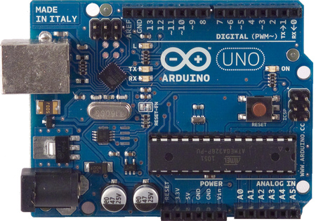
The Uno should be a fairly familiar board if your into electronics. Its one of the first boards released by the Arduino company: early versions had D-sub interfaces, migrating to USB and eventually to the current Rev 3 boards and some SMD editions.
 |
| Early Arduino Uno - Wikipedia |
 |
| Later Versions had USB |
 |
| The Rev 2 (Version I own) notice the interface chip next to TxRx LED's is offset 45degrees |
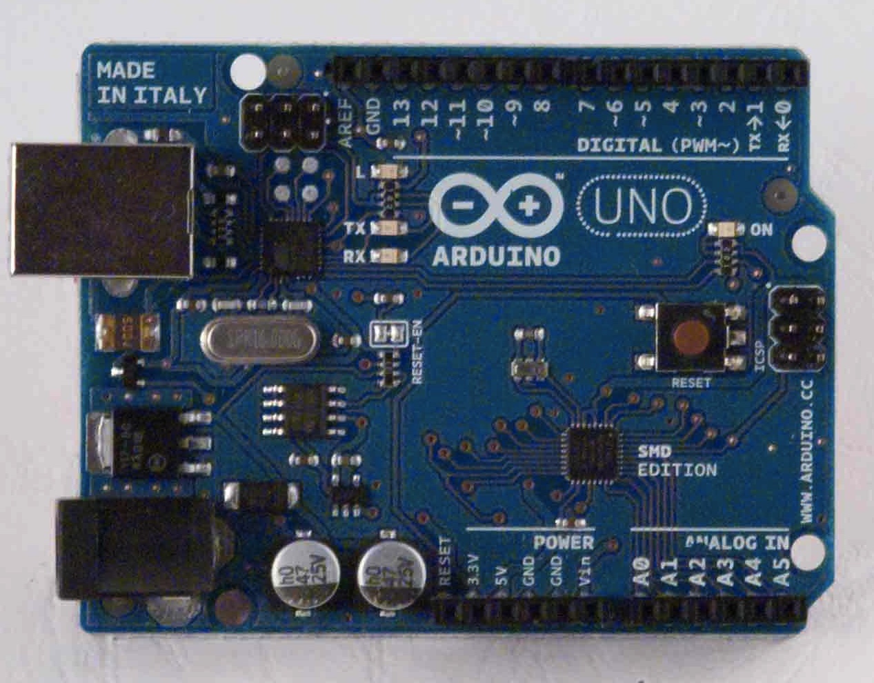 |
| SMD Edition |
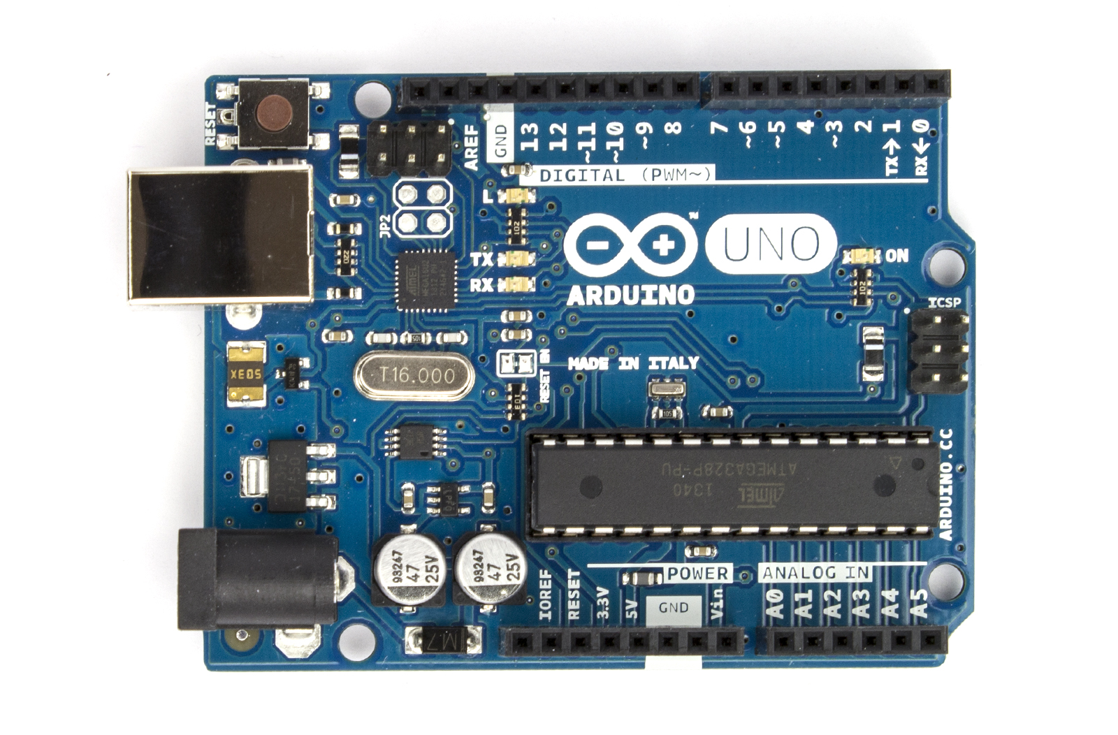 |
| The Rev 3. Notice the position of the reset button |
There are also loads of Rip-off versions, nothing wrong with them, they may be cheaper, but I prefer going with the real deal.
I have the Rev 2, based around the Atmel ATMEGA328P: 28-pin DIP, 8-bit micro controller. Beauty of this version is if the chip blows, you can buy a new one either programmed or un-programmed and swap it out. If its un-programmed, you will need to program a bootloader to it through the ISCP header: Olimex Programmer Review
However, on mine, A0 is busted. So in the meantime until I get another chip ordered, I thought I'd figure out a way of how to get more out of the other analog inputs.
A simple way of doing this is to use an analogue switch IC. You can use a multiplexer, but analogue switches can usually work both ways, whereas multiplexer & demultiplexers can only usually work in one way. Also make sure you have an analogue switch or mux/demux for analogue applications and, digital ones won't work as required!
As mention above, analogue switches work both ways, so you can have one input accepting a number of sensors, for example, or have 4 inputs from 1 sensor. Also they can be good for auto-ranging circuits or gain adjustments circuits, by clicking in more or less feedback resistance.
The Setup & Code
I'm basing this around a DG409. Its an array of analog switches in various configurations. The 409 is 2 sets of Single Pole, Quad Throw (SP4T) switches. Each position is selected by the address pins A0 & A1. Its all there in the datasheet.
With this I was able to connect up a number of sensors to one bank of switches:
- S1A: pull-down switch
- S2A: A voltage divider (div. 10) from a higher voltage supply
- S3A: An LDR
- S4A: a Pot
I then connected the pin DA to the analog input and some digital pins to the address pins A0 & A1 of the DG409. The full setup is shown here:


I'm using an interrupt switch on pin-2 so I can cycle through the different sensors at any time.
The COM or output of the DG409 (white wire) is connected to the A1 analogue input of the UNO. This now essentially has 4 inputs now on one analogue input! All i have to do is program a way to change the address each time I press the interrupt switch.
I managed to punch out some code in under 15 mins:
So a breakdown of the code:
So in this case at 30V my full scale was 574.;
574/1023 x 5V = 2.8V;
2.8 x 10 = 28V, well I did have the fine adjustment turned down (its an old supply) so I'll take that as correct!
However there are limitations:
The COM or output of the DG409 (white wire) is connected to the A1 analogue input of the UNO. This now essentially has 4 inputs now on one analogue input! All i have to do is program a way to change the address each time I press the interrupt switch.
I managed to punch out some code in under 15 mins:
So a breakdown of the code:
- In the setup I have declared some pins as outputs, set pin 2 as the pin to activate the ISR (Interrupt service routine - https://www.arduino.cc/en/Reference/attachInterrupt), and started the serial monitor going.
- I then declare the integer sens to be used to select the address of which switch to select on the DG409
- The loop basically reads the analogue input A1 and prints it on the serial monitor whilst also printing which sensor its looking at. it does this every 500ms using delay(500);
- The ISR is where most of the work is:
- 1st it checks if the integer sens is less than 3, if it is then it can be incremented
- if it is not less than 3, it resets it back to 0 again.
- it then checks the value of sens using a switch-case and sets the outputs 8 & 9 to the appropriate logic, and therefore address for the DG409 - truth table of addressing can be seen in datasheet.
So in my example, sens: 0 = pulldown switch (addr: 00), 1 = divide by 10 circuit connected to a 30V variable supply (addr: 01), 2 = LDR (addr: 10), 3 = pot (addr: 11).
Results
Uploaded the sketch and opened the serial terminal:
 |
| Pressed the pull down switch for about 5 seconds |
 |
| Adjusted the 30V supply from 30V down to 0V |
574/1023 x 5V = 2.8V;
2.8 x 10 = 28V, well I did have the fine adjustment turned down (its an old supply) so I'll take that as correct!
 |
| The LDR output. Here I was moving my hand over the LDR |
 | |
| POT adjustment, rotating to both ends. |
It all works as expected. So that's a win in my books.
Conclusions
Well it works, its pretty simple to do and you can get a lot more I/O for very little extra cost and effort.However there are limitations:
- Time frame & speed limits - if the sensors require fast monitoring, and you have 4 of them, then you have to switch between them all really quickly.
- This takes time and to get an accurate reading at a given time frame (say 1uSec) and the time it takes to go through them all takes 10uSec, then your going to loose some data on that sensor whilst reading the other sensors - so bear this in mind.
- Make sure your sensors a slow when compared to the speed of the UNO (or whatever board your using) or utilise some sort of averaging in your programming.
- Giving up some digital IO - ok its only 2 pins! But if your applications uses lots of digital signals, then you might have to work out some sort of addressing or serial interface to your analogue switch, or find a switch with some serial interface.
Changes?
So why did I use the ISR: well because between each reading I was waiting 500ms, which is quite a long time, so I needed to interrupt right in the middle of a delay function, rather than wait 500ms to check a change in state of the sensor select button.I could have just collected the data from all the sensors and spat them at the serial terminal in one go, that too would have been quicker.
I did originally use some port manipulation to set the address of the switch. but that meant a lot of pins weren't being used and would look somewhat intimidating to noobs. Have to be efficient yet friendly. Though if any noobs are reading this then: seriously, click on the link and go tinker, its a function worth knowing.
Anyway, this should help if you are looking to get more I/O out of your UNO, or any dev. platform. Go have fun!
Hey nice project!
ReplyDeleteHow did you find the fritzing part for dg409?